
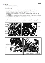
[4] DISASSEMBLY/ASSEMBLY
[4]-3. Clutch, Ratchet
R
epair
P
7
/
19
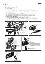
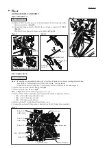
(1) Remove Cutting device. Refer to the clause of
[4]-1
.
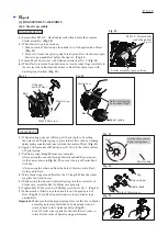
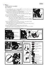
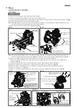
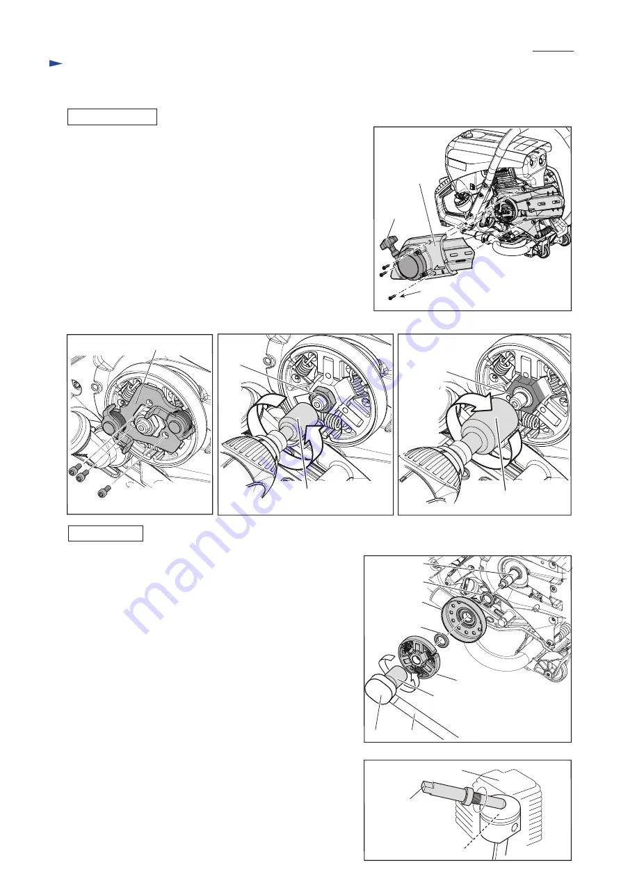
(2) Loosen three M5x12 Hexalobular socket head bolts, then remove
Clutch cover together with Starter assembly. (
Fig. 16
)
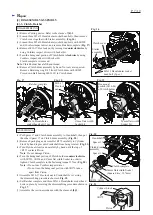
(3) Loosen three M5x16 Hexalobular socket head bolts with 1R290
and Cordless impact driver, and remove Ratchet complete. (
Fig. 17
)
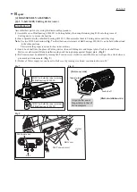
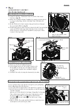
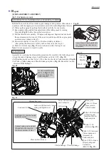
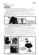
(4) Remove M10-17 Hex lock nut by turning it
counterclockwise
by
using Cordless impact driver with Socket bit.
(5) Turn the hexagonal portion of Clutch holder
clockwise
by using
Cordless impact driver with Socket bit.
Clutch complete is removed.
Note
: Clutch holder has a left hand thread.
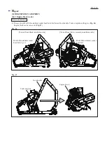
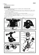
(6) Remove Clutch drum assembly by hand. No tools are required.
Remove Retaining ring R-35 from Clutch drum with 1R005.
Press down Ball bearing 6003LLU in Clutch drum.
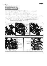
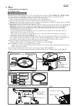
(1) Put Spacer 17 and Clutch drum assembly to Crankshaft, then put
the other Spacer 17 on Clutch drum assembly. (
Fig. 20
)
(2) Remove Spark plug and assemble 1R372 carefully to Cylinder
block by hand to prevents Crankshaft from being rotated. (
Fig. 21
)
(3) Turn Flywheel slowly and carefully by hand until the top of
1R372 contacts Piston.
Note
: Do not damage Piston.
(4) Turn the hexagonal portion of Clutch holder
counterclockwise
with 1R223, 1R224 and 17mm flat width Socket in order to
tighten Clutch complete to the fastening torque 38N.m. (
Fig. 20
)
Note
:
•
Do not use Cordless impact driver.
•
Do not turn the hexagonal portion with 1R372 taken
apart from Piston.
(5) Assemble M10-17 Hex lock nut to Crankshaft by reversing
the disassembling procedure shown in
Fig. 18
.
(6) Set Ratchet complete and three M5x16 Hexalobular socket head
bolts in place by reversing the disassembling procedure shown in
Fig. 17
.
(7) Assemble the rest in accordance with the clause of
[4]-1
.
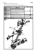
Fig. 16
Fig. 20
Fig. 21
DISASSEMBLING
ASSEMBLING
Fig. 17
Fig. 18
Fig. 19
U-shaped notch
of Reel
Clutch cover
Starter
assembly
M10-17
Hex lock
nut
17mm flats width
Socket bit
M5x12 Hexalobular socket
head bolt (3 pcs.)
M5x16 Hexalobular
socket head bolt (3 pcs.)
Ratchet complete
Hexagonal
portion (M16-24)
of Clutch holder
24mm flats width
Socket bit
24mm flats width Socket
(Square drive: 12.7mm)
Crankshaft
Cylinder block
Piston
Spacer 17
1R372
1R224 1R223
Spacer 17
Clutch drum
assembly
Clutch complete


