
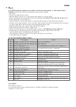
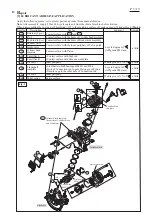

[4] DISASSEMBLY/ASSEMBLY
[4]-8. Engine (cont.)
R
epair
P 1
5
/
19
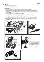
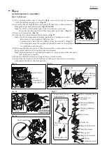
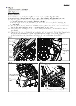
DISASSEMBLING
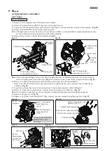
Fig. 54
Note
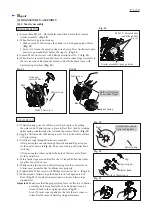
: Cam gear assembly functions as automatic decompression valve system.
Valve is slightly open to release the compressed air in Engine at the starting time, before moving fly weight
by centrifugal effects. It means the insufficient setting of Cam gear assembly will cause engine stall/ extreme
reaction force at engine running due to too much load by the compressed air.
(11) Remove Pin 5 that sets Rocker arm assembly in place on Cylinder head complete. (
Fig. 54
)
Use 1R308 to push out Pin 5.
The distinction of Rocker arm assembly and Push rods (for use of the exhaust system/ intake system) enables you
shortens the repair process (Gap adjustment between Rocker arms and Retainers is even difficult, however, you can
adjust it by using 1R366. Refer to
Fig. 68
.
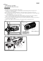
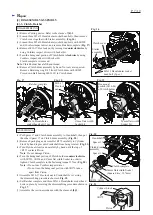
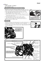
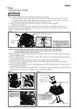
Important:
D
isassemble the parts in the room on Cylinder head complete before removing it and
clean the clogged portions in the following steps. You may repair successfully without
doing the step (5) and later in the next page.
(1) Remove Rocker cover complete, then push out Pin 5 on hinge for Rocker arms with 1R308 and remove Rocker arms.
(Refer to
Figs. 50
and
54
)
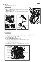
(2) Remove Spark plug. Turn Flywheel until Piston comes to the upper dead point by looking through Spark plug hole
on Cylinder head complete.
Note
: Align the rib as a mark on Flywheel with the rib on Cylinder block as drawn in
Fig. 55
.
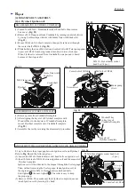
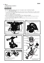
(3) Insert a bent Lead wire #16 into Combustion chamber through Spark plug hole so that Valves do not fall into
Combustion chamber. (
Fig. 56
)
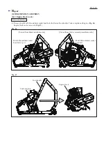
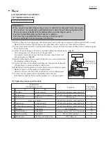
(4) While compressing Compression spring 11 by pushing Retainer with 1R003 attached with 1R389, remove Cotter by
a thin bit magnetized by 1R288.
Routes in Cylinder head complete, the upper surface on Valves and the room on Cylinder head complete can be clean
through removal of four Cotters, two Retainers, and two Compression springs 11.
Fig. 55
Fig. 57
Fig. 56
1R389
1R003
Rocker arm assembly
Exhaust
push-rod
Pin 5
Cylinder head
complete
Intake
push-rod
Intake
system
Exhaust
system
Rib on Flywheel
Rib on Cylinder block
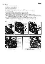
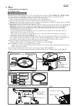
Retainer (2 pcs.)
Cotter (4 pcs.)
[viewed from the upper side of the room]
Compression
spring 11 (2 pcs.)
Intake valve
Exhaust valve
Cylinder head complete
Note
: Intake system of Rocker
arm has to be close to
the hole of Cylinder head
complete.
the hole of Cylinder head complete
Use Cotter removal
attachment to push
Retainer.
Note
: Intake valve has to
be close to this hole
of Cylinder head
complete.


