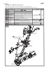

[4] DISASSEMBLY/ASSEMBLY
[4]-8. Engine (cont.)
R
epair
P 1
7
/
19
Note:
Be sure to apply Makita grease N No.2/ 4-cycle engine oil in accordance with
[3] LUBRICANT APPLICATION
.
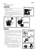
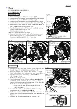
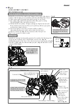
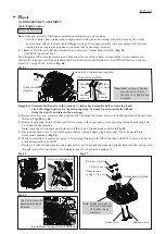
(1) Connect Piston with Crankshaft complete by inserting Piston pin into place; there is no front/back to Piston.
(2) Secure Piston pin by mounting Ring spring 12 onto each end of Piston pin.
Note:
The ring gap of Ring spring 12 can be positioned at any angle to Piston pin.
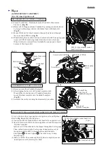
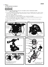
(3) Install Oil ring in the grooves of Piston; Side rail first, Spacer next, then the other Side rail.
Important:
Be sure to fit the three rings with the ring gaps at 120 degrees to one another as shown in the left of
Fig. 63
.
(4) Install Second ring first then Top ring in the groove of Piston.
Important 1:
Be sure to fit the two rings with the ring gaps at 180 degrees to each other as shown in the right of
Fig. 63
.
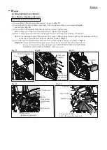
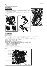
Important 2:
Second ring has a taper face and must be installed with the large diameter facing Oil ring. (
Fig. 64
)
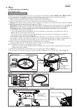
Distinguishing between Top ring and Second ring & Discriminating the larger diameter of Second ring:
If both of the two rings are new and unused,
•
You can distinguish from their appearances; there is a red marking on the side face of Second ring as shown in
Fig. 65
while not on the side face of Top ring.
•
You can face the large diameter of Second ring by placing Second ring with the red marking on your right and
with the ring gap near you as shown in
Fig. 65
.
If both of the two rings are used and the white marking of Second ring is rubbed off, carefully press the side face of
the two rings to the inner wall surface of Cylinder. You will be able to distinguish the two rings or to discriminate the
large diameter of Second ring through the differences in contact feelings that the different side faces make.
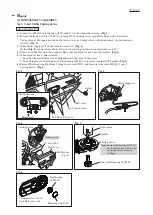
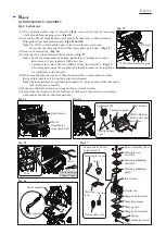
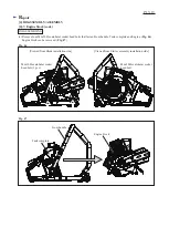
(4) Remove oil/grease from the mating surface of Cylinder block and Crankcase.
Then apply ThreeBond 1215 to the mating surface of Crankcase as shown in
Fig. 66
.
Note
: ThreeBond 1215 must not be applied to Oil supply routes.
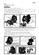
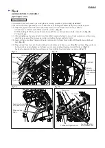
Apply 4-cycle engine oil to the cylinder portion of Cylinder block, and then while compressing Piston rings, mount
Cylinder block onto Crankcase.
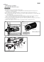
(6) Tighten eleven Hexalobular socket head bolts in a crisscross pattern. (Refer to
Fig. 58
.)
(7) Do not forget to set Exhaust port spacer in place on Muffler installation side of Cylinder head complete. (
Fig. 67
)
Fig. 67
Fig. 63
ASSEMBLING ENGINE BLOCK
Top ring
This mark can be
ignored for
assembling
EK7650H/ EK7651H.
Second ring
Fig. 64
Fig. 66
[Crankcase viewed from top]
Portion to apply
ThreeBond:
indicated in gray
Oil supply routes
Fig. 65
Top ring,
with barrel face
Second ring,
with taper face
Side rail
Side rail
Spacer
Oil ring
ring gap
ring gap
Second ring
red marking
Oil ring
ring gap
ring gap
ring gap
Side rail
Side rail
Spacer
Exhaust port spacer
Cylinder head complete


