
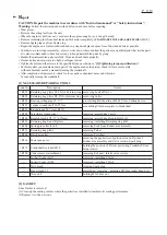

[4] DISASSEMBLY/ASSEMBLY
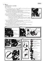
[4]-6. Throttle lever
R
epair
P 1
2
/
19
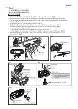
DISASSEMBLING
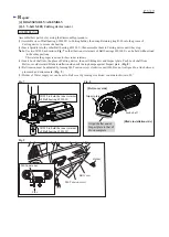
DISASSEMBLING
Fig. 42
Fig. 43
Fig. 44
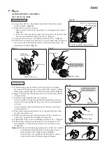
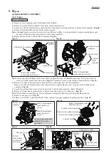
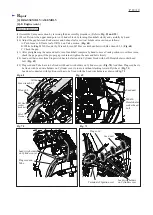
(1) Remove Pin 5 from the grooves on Tank complete by levering it up with a
slotted screwdriver. (
Fig. 42
)
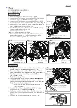
(2) Expand the hinge portion for Throttle lever on Tank complete with 1R003.
(
Fig. 43
)
Throttle lever section can be removed as drawn in
Fig. 44
.
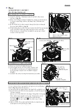
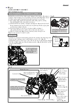
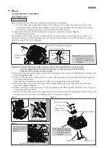
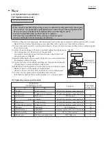
Note
:
•
It is highly recommended to drain the oil system of Engine block before starting disassembling
because the oil remaining there will drip out to delay your operation.
•
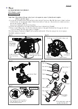
When Piston section is repaired, it is necessary to remove Engine from Tank complete.
(1) Remove Hood section. Refer to
Fig. 4 of [4]-1
.
(2) Remove Carburetor. Refer to
[4]-5
.
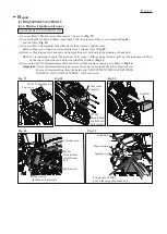
Refer to
Fig. 45
and do the following steps (3), (4), (5).
(3) Remove three Tubes’ ends that come from Cylinder block complete as follows:
• Tube 3-170 with Clamp to Rocker cover
• Tube 3-130 to Hose joint in Seal
• Tube 3-75 to Hose joint in Seal
(4) Remove Tube 5-70 with Clamp from Rocker cover.
(5) Loosen Hose clamp 30 then remove Suction line from Cylinder block complete.
Fig. 45
Pin 5
Pin 5
Lock off lever
Torsion
spring 12
Expand the hinge portion carefully.
1R003
Throttle lever
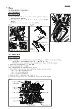
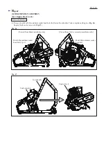
[4]-7. Engine block
Tube 3-170
with Clamp
Tube 3-130
Seal with Joints
Rocker cover
Suction line
Hose clamp 30
Cylinder block
Tube 5-70
with Clamp
Tube 3-75


