


P 9/ 15
Note
: Drain Fuel tank before disassembling Carburetor.
See
Fig. 22
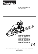
. (1) Remove Hood.
(2) Turn Choke lever to the position of “STOP”.
(3) Remove two M4x40 Hexalobular socket head bolt on Intake manifold.
(4) Remove Air filter cover, Air filter, and Intake manifold.
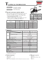
(5) Remove one end of Tube 3-70 and one end of Tube 2.5-72 from Carburetor. (
Fig. 23
)
Note
: Gasoline is left in Tube 3-70, and therefore, clean the gasoline with a cloth.
(6) Remove Carburetor from Throttle linkage.
Note
: When setting Carburetor in place, hook Throttle linkage to the hole of Lever-throttle (designated by Black arrow in
Fig. 22)
.
Fig. 22
Fig. 23
R
epair
DISASSEMBLING
[2] DISASSEMBLY/ ASSEMBLY
[2]-9. Ignition coil
5.5x16 Hexalobular
tapping screw (2 pcs.)
Choke
lever
Intermediate
flange
5.5x16 Hexalobular
tapping screw (2 pcs.)
Contact spring
3x10 Tapping
screw
Cable harness
Stop
mark
Air filter
cover
Tube 2.5-72 removed from
Carburetor
Tube 3-70
removed from
Carburetor
Air filter
Intake
manifold
Refer to
Figs. 20 and 21.
(1) Insert two Isolating washers into two seated holes of Cylinder.
(2) Pretighten Ignition coil in place by tightening two M5x20
Hexalobular socket head bolts through Isolating washers.
(3) Insert 1R366 between Ignition coil and Flywheel and adjust
the clearance of 0.25 to 0.3mm as follows:
• Once unscrewing two M5x20 Hexalobular socket head bolts,
Push Ignition coil toward Flywheel carefully and check the
clearance. If the above clearance is obtained, tighten the bolts
to fastening torque 5 ± 0.5 N·m.
(4) Connect Flag terminal of Cable harness to Ignition coil.
(1) Remove Sprocket guard, Guide bar and Saw chain from
the machine.
(2) Remove “Recoil starter section”. See
[2]-7.
(3) Remove Flag terminal on one of cable end from Ignition coil.
Note
: The other cable end cannot be removed from Ignition coil
because they are integrated as a Cable harness.
(4) Remove two M5x20 Hexalobular socket head bolts. (
Fig. 20
)
Ignition coil with Cable harness is removed from Flywheel.
(
Fig. 21
)
Note
: Do not lose two Isolating washers between Cylinder
and Ignition coil. (
Fig. 21
)
DISASSEMBLING
ASSEMBLING
Fig. 20
Fig. 21
Flag terminal
of cable harness
Flag terminal of Cable harness
for connecting with Ignition
Isolating washer (2 pcs.)
Cable harness
Cylinder
Ignition coil
Ignition coil
Flywheel
M5x20
Hexalobular
socket head
bolt (2 pcs.)
M5x20
Hexalobular
socket head
bolt (2 pcs.)
0.25 to 0.3mm
[2]-10. Air filter, Carburetor, Intermediate flange