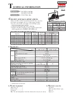
background image

P 11/ 15

See 

Figs. 28 and 29 

for the positions of Needle-idle (L)  and Needle-high speed (H).

Carburetor has two different specifications (Walbro-made and ZAMA-made). 

After tightening each Needle to the full, loosen them as listed below.

Fig. 28

Fig. 29

R

epair

Needle adjustment

Pressure test

General check

[2] DISASSEMBLY/ ASSEMBLY

[2]-10. Air filter, Carburetor, Intermediate flange (cont.)

Fig. 30

Fig. 31

(S)

L

H

(1) Connect 1R127 to Carburetor. (

Fig. 29

)

(2) Push up the air pressure until the pressure gauge indicates 

      0.05 Mpa.

(3) The carburetor is in order if the air pressure can be kept for

     10 seconds.

Note

: If the air pressure drops, check the following conditions.

          • Valve-inlet needle: if necessary, Spring, Lever-metering,

             Pin-metering lever, and Plug-welch have to be replaced

             together. (

Fig. 30

)  

          • Dirt/ deposits on the top of Valve-inlet needle: clean it. 

          • Gasket pump and Diaphragm-pump: replace them 

             with the new ones.

• Inlet screen should be clean. 

• Pulse hole should be clean.

Check around Valve-inlet needle and Lever-metering

Check Diaphragm-pump

Check Diaphragm assembly-metering

Refer to 

Figs. 30

 and 

31

.

Check that the tip of Valve-inlet needle is not worn.

Replace it the new one if it looks worn.

Check that Lever-metering is not worn and it is assembled

properly as drawn in 

Fig

31

.

Note

: Low position of Control lever causes;

          • Insufficient fuel circulation

          • No maximum power

         High position of Control lever causes;

          • Carburetor flooding

          • Starting problems

          • Poor idling

          • Poor acceleration

If necessary, reassemble them properly / replace them with 

the new ones.

• When Diaphragm-pump is dented, torn, or creased,

• When the valve flaps of Diaphragm-pump are bent,

replace Diaphragm-pump and Gasket-pump with new ones.

• (i) When Diaphragm assembly-metering is dented, hardened, 

       or torn,

  (ii) If there is a visible wear on the button of Diaphragm 

        assembly-metering

• If Diaphragm assembly-metering lacks elasticity, replace 

   Diaphragm assembly-metering and Gasket-metering diaphragm 

    with new ones.

Connect 1R127

to the fuel nipple.

1R127

Push

Carburetor 

Spring

Plug-welch

Lever-metering

Pin-metering lever

Valve-inlet needle

Inlet screen

Diaphragm-pump

Gasket pump

Gasket-metering 

diaphragm

Diaphragm 

assembly-metering

Pulse hole

Screw-idle adjustment (S)

Needle-idle

L

Needle-high speed

H

Correct

Too high

Too low


(Position of Lever-metering)

ZAMA

Walbro

1-1/4

1-1/2

2

4-1/4

L-needle

H-needle

Note

: Adjust the rpm from the above setting positions with 1R070.

Summary of Contents for EA3200S

Page 1: ...hragm Carburetor Yes Primer pump Yes Rotation limiter Yes Clutch Yes Catalytic converter In compliance with exhaust emission regulations EPA Phase 2 EU Stage 2 Engine Displacement cm cu in Fuel 2 stro...

Page 2: ...ssembling Hexalobular socket head bolt Torque wrench shaft 20 90N m 1R223 Torque wrench shaft 2 6N m 1R254 adjusting a proper gap between Flywheel and Ignition coil Feeler gauge set 1R366 Hexalobular...

Page 3: ...f Clutch drum assembly do not have damage wear Fig 5 Inside Chain sprocket portion Needle bearing portion If there is damage wear on Clutch dram assembly replace it to new one 2 Apply a little amount...

Page 4: ...starter section 9 Remove 4 7x16 Hexalobular tapping screw and Flat washer 5 from Starter complete installation side on Hand guard Fig 7 10 Remove Stop ring E 4 from Pin A of Engine housing complete F...

Page 5: ...areful to each direction Note Wear gloves for safety Be careful that Muffler stays very hot for a while after running the engine Fig 9 Repair DISASSEMBLING 2 DISASSEMBLY ASSEMBLY 2 4 Muffler section A...

Page 6: ...wo Clutch shoes Fig 13 Be careful to the hooking direction of Tension springs 5 When one of Tension spring 5 has a damage replace two Tension springs 5 with the new at the same time Do not replace the...

Page 7: ...s are fit into two slits of Oil pump body If this way is difficult push Piston slightly in the direction of Body Note When set Oil pump complete in place turn Adjusting screw counterclockwise to the f...

Page 8: ...f Rewind spring as follows After making the slack of rope between Starter grip and Reel put the slack into the groove of Reel and pull the starter grip lightly Note Be sure to loosen the spring force...

Page 9: ...ning two M5x20 Hexalobular socket head bolts through Isolating washers 3 Insert 1R366 between Ignition coil and Flywheel and adjust the clearance of 0 25 to 0 3mm as follows Once unscrewing two M5x20...

Page 10: ...lange Notch of Choke lever 5 5x16 Hexalobular tapping screw 2 pcs Tube 2 5 112 to Fuel nipple Contact spring 3x10 Tapping screw Grounding wire of Cable harness Tube 2 5 72 removed from Carburetor Guid...

Page 11: ...lve inlet needle is not worn Replace it the new one if it looks worn Check that Lever metering is not worn and it is assembled properly as drawn in Fig 31 Note Low position of Control lever causes Ins...

Page 12: ...ion of Tank assembly 2 Set Catch lever to the hinge position of Tank assembly Fig 35 Note Torsion spring 10 has to be hooked with Throttle lever as drawn in Fig 36 See Fig 33 and the explanation Assem...

Page 13: ...ortant Supply Soap liquid onto the suspicious surface of Fuel leakage during the pressure test After the above steps reverse the disassembling procedure of DISASSEMBLY of 2 11 Tank assembly Pick up Ga...

Page 14: ...side Be sure to use New Gasket Fig 10 and New Crank case sealing When replacing Ball bearing 6201 press fit the inner ring portion to Crank shaft using the same size pipe and a block for placing the c...

Page 15: ...Muffler complete and Cooling plate 266605 8 2 M5x16 Hexalobular socket head bolt 8 1 266606 6 1 M5x40 Hexalobular socket head bolt 8 1 Carburetor 266604 0 2 M4x40 Hexalobular socket head bolt 3 0 5 C...

Reviews: