Support
Brush
holder
P 9 / 14
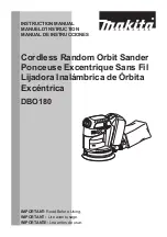
C
ircuit diagram
Controller
2
3
4
1
Insulated
terminal
Insulated
terminal
Noise
suppressor B
Noise suppressor A
Power supply cord
Choke coil
Switch
Support
Color index of lead wires
Black
White
Orange
See-through
Purple
Connect to
field core.
They are put in the rear side
of switch ( cord guard side), which
are not used in some countries.
Noise suppressor is not used for some
countries, or 2 wires type of noise
suppressor is used for other some countries.
White or blue
White or black
Brush
holder
Black or brown
White or blue
Controller
Insulated terminal
to support
BO4900V
Note in repairing
Brush
holder
Do not directly connect the field lead wire (purple) and
controller lead wire (white or blue) to brush holder.
Cut the field lead wire (purple) and connect it to
controller lead wire (white or blue) with insulated
terminal, and connect the insulated terminal to brush
holder with the other piece of field lead wire (purple).
Field lead wire (purple)
Other piece of field
lead wire (purple)