W
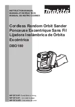
iring diagram
P 10 / 14
BO4900V
Controller
Controller
Support lead
wire (purple)
Controller lead
wire (black)
Controller lead
wire (white or blue)
Fix lead wires
with lead holder.
Do not slack the lead
wires between this line.
Controller
lead wire
(white or blue)
Before installing controller, fix the
lead wire (white or blue) with
lead holder as illustrated above.
Put slack portion of lead wires
into this space.
Put the following parts in the rear side
of switch ( cord guard side).
* Noise suppressor B
* Choke coil
* Insulated terminal
They are not used for some countries
**Noise suppressor A is not used
for some countries, or 2 wires type
of noise suppressor is used for other
some countries.
* Insulated terminal
* Noise suppressor B
* Choke coil
** Noise suppressor A
Inflect this switch terminal
to set noise suppressor.
Fix lead wires
with lead holder.
Fix lead wires
with lead holder.
Fix lead wires with lead holder.
Put the insulated terminal
in this space.
Fix lead wires
with lead holder.
Pass 2 support lead
wires inside of pin.
Grounding lead wire
of noise suppressor
(see-through)
Support lead wire
(white or black)
Support lead wire
(black)
Support lead
wire (orange)
Controller lead
wire (orange)
lead holder
Refer to "Note in repairing" at page 9.
Controller
Insulated terminal
Field lead wire
(purple)
Lead wire (purple)
(other piece of
field lead wire)
Controller lead wire
(White or blue)
Controller lead wire
(White or blue)
Fix the lead wires
with lead holders.