background image

20

Kleiss MCS60-1016 System Manual  v.15 June 2020 

|

www.MainlineControlSystems.com

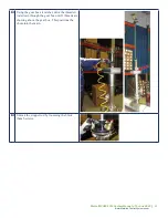
Attach bridge stands (both rods) to top of drilling 

dome.

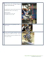
Make sure the slide gate valve is open.

Pull out the bayonet lock on tapping device and 

lower drilling rod until pilot drill touches the 

surface of the pipeline to be tapped.

When doing this, make sure the bayonet lock is in 

a free position and does not lock into the drilling 

rod.

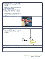
After the pilot drill is in contact with the pipeline, 

lock the feed tube to the drilling rod at the closest 

hole on the drilling rod using the bayonet lock. Do 

this by either rotating the feed tube until it locks in 

place or pulling up on drilling rod.

Locked

Summary of Contents for Kleiss MCS60-1016

Page 1: ...Kleiss MCS60 1016 System Manual Flow Stopping System 10 16 18 PE up to 60 psi Flow Stopping System 10 16 18 PE up to 60 psi...

Page 2: ...10 to 16 18 PE on all pipe material cast iron polyethylene steel and PVC pipes To accommodate the various pipe materials and sizes the tapping tool and stopping tool are outfitted with the appropriat...

Page 3: ...fety factor to allow 10 6 psi for operation on 60 psi MAOP systems or in abnormal operating conditions D Tool to fitting connection of 4 ANSI 150 flange 2 2 Tapping Tool and Completion Tool Kit Specif...

Page 4: ...t F By pass vent port a Full 4 ANSI 150 3 3 4 tap size b 4 ANSI 150 flange connection 2 4 MDS Inflatable Stopper Specifications 2 4 MDS Inflatable Stopper Specifications A Sizes a 8 85 10 82 225 mm 27...

Page 5: ...s important to understand the MCS stopping tools and their operation completely It is also important to understand the complete job and sequence of steps to perform a safe stop Safety of the operators...

Page 6: ...s flow first 2 Always insert first inflatable stopper WITH the flow of gas 3 Always inflate the stopper as quickly as practical 4 Suggested stopper setting sequence is tower 1 2 3 4 Set all 4 stoppers...

Page 7: ...e on both sides of the stopper before deflation or removal 1 Deflate stoppers 2 and 3 2 Use by pass vent ports on tower 1 and 2 to equalize pressures on stoppers 1 and 4 Equalize slowly 3 Use by pass...

Page 8: ...other initiate the by pass flow first 2 Always insert first inflatable stopper WITH the flow of gas 3 Always inflate the stopper as quickly as practical 4 Suggested stopper setting sequence is tower 3...

Page 9: ...on or removal 1 Deflate stopper 2 2 Back pressure stopper 4 through the system pressure ports in towers 3 and 4 3 Deflate stopper 4 4 Equalize pressure on stoppers 1 and 3 through the by pass vent por...

Page 10: ...f 2 8 14300054 Steel and Cast Iron Pilot Drill requires adapter 9 10310785 Pilot Drill Adapter 3 4 to M12 10 13200727 PE and PVC Pilot Drill 11 11000120 Ratchet square 20 mm PART DESCRIPTION 12 131001...

Page 11: ...nents Tapping Tool and Completion Tool Components Drilling Dome Air Motor Ratchet Cutters Feeding Rod with Bridge Tapping Device Hot Tap Tool Plug Spindle Assembly Pilot Drill Plug Spindle Handle Dril...

Page 12: ...6 7 8 10 13 14 15 16 17 11 9 12 18 19 20 PART DESCRIPTION 1 12241300 Chute 1 2 12242000 Slide Gate Valve 3 12241310 Chute 2 4 12241320 Chute 3 5 11000201 Wrench 41 mm set of 2 6 94200020 Silicone Gre...

Page 13: ...s com Stopping Tool Components Stopping Tool Components By Pass Vent Port System Pipeline Pressure Gauge Stopping Tower Safety Fitting Chute MDS Stopper Slide Gate Valve Gear Box Assembly Internal Sto...

Page 14: ...Stopper size 9 84 12 40 250 mm 315 mm with Shock Absorber Hose 3 23101359 MDS Stopper size 12 40 15 74 315 mm 400 mm with Shock Absorber Hose Fitting Completion Plug Blind Flange Stud Bolts Fitting Co...

Page 15: ...8 connection 6 12242210 Hand Pump Adapter 7 99000705 Safety Fitting gold claw 8 12100740 Safety Fitting silver 9 BPGT 1 By Pass Gauge Tree 10 BPC 1 By Pass Cap 11 BPVA 1 By Pass Vent Adapter 12 BPT 1...

Page 16: ...5 13200725 13200725 13200725 13200725 Pilot Drill 14300054 14300054 14300054 14300054 14300054 Pilot Drill Adapter 10310785 10310785 10310785 10310785 10310785 Chute 12100450 1 12100460 2 12100470 3 1...

Page 17: ...on your electrofusion processor that will fit the 4 0 mm pins When installing PE fittings as part of the electrofusion process make certain to allow the fitting to completely cool down for the entire...

Page 18: ...tapping tool by attaching the dome adapter ring to the drilling dome Tighten the connection by means of the hook assembly wrench Thread the tapping device on to the dome adapter ring by means of the h...

Page 19: ...the drilling rod Figure B PE cutter 13100100 and pilot drill 13200727 Secure the pilot drill using the set screw on the drilling rod A B If cutting through steel or cast iron grease the cutter and pi...

Page 20: ...em Manual v 15 June 2020 www MainlineControlSystems com Attach complete tapping tool with gasket in place to top of slide gate valve using nuts and washers Check gasket Position feed tube so it is flu...

Page 21: ...g rod until pilot drill touches the surface of the pipeline to be tapped When doing this make sure the bayonet lock is in a free position and does not lock into the drilling rod After the pilot drill...

Page 22: ...not on the pipe and is in the proper position to start drilling Rotate Place air motor on drilling rod square Operator should ensure the air compressor is working properly at 90 psi measured at the i...

Page 23: ...ast iron Continue to lower the feeding rod from above with bridge as the air motor lowers to keep the air motor centered and stable The tapping procedure is finished when the drilling rod can rotate w...

Page 24: ...valve If assistance to get the cutter out is needed turn the drilling rod clockwise NEVER turn the drilling rod counterclockwise This can damage the cutter Be aware of the fact that the pressure insid...

Page 25: ...ols Coupon Remover 13605135 to remove the coupon from the cutter After tapping steel pipe to remove steel shavings from interior of pipe use the magnetic spindle in combination with the drilling dome...

Page 26: ...e condition of the gasket can be verified when conducting the vacuum test on the stopper prior to inserting the stopper into the gas system NOTE Extra stopper rod gaskets should always be available Ne...

Page 27: ...wrenches to ensure tight connection and seal Attach hand pump adapter to inflation pressure port This is the offset connection Connect hand pump to hand pump adapter With the valve open pull a vacuum...

Page 28: ...d or a MDS Stopper Test Adapter 12242200 After the stopper stabilizes wait a minimum of 10 minutes to make certain the same pressure is maintained within the MDS Stopper NOTE Do not inflate the stoppe...

Page 29: ...ection as arrow on tower Pull stopper up into tower ALTERNATE STOPPER ATTACHMENT Stopper may be attached to stopper rod and inserted through the top of the tower instead of being pulled up into the to...

Page 30: ...r with silicone spray Next push the stopper into the tower until black cap is flush with the tower Flip the bolts to the top of the black cap and tighten wing nuts Lock the stopper rod by tightening t...

Page 31: ...he bottom of the stopping tower There is only one way to connect the chute properly and that is to match the pin and the indent in the tower Using the same Kleiss silicone spray you used on the stoppe...

Page 32: ...flow stopping tool to top of slide gate valve using nuts and washers Check gasket Attach by pass vent port with gasket in place to the side of the flow stopping tool using stud bolts Make certain port...

Page 33: ...MainlineControlSystems com Using the gear box air ratchet drive the threaded rods down through the gear box until 3 threads are showing above the gear box This positions the chute into the main Unloc...

Page 34: ...n inserting Stop pushing the stopper rod downwards when the depth indicator mark is at the black cap Depth Indicators Use top line for 12 to 18 pipe Use bottom line for 10 pipe Lock the stopper rod by...

Page 35: ...o ensure the best seal on pipeline wall NOTE If 120 psi is not obtainable then inflate to a minimum of 2 times system pressure to achieve stop off Install safety fitting on inflation pressure port All...

Page 36: ...This can be done in a variety of ways Refer to examples in Section 3 0 of this manual and your gas company procedures ALWAYS EQUALIZE PRESSURE Remove safety fitting from inflation pressure port Attach...

Page 37: ...ystems com Unlock the stopper rod by loosening the black thumb screws Pull the stopper rod completely upwards You may need to use some force to do this Hint If you feel some resistance use the jack as...

Page 38: ...as shown and lifting up to compress the spring Then push the jack assist to slide it along the stopper rod Once on top of the tower insert the jacking handle as shown and begin jacking until the pres...

Page 39: ...eControlSystems com Close slide gate valve Disconnect equalization hose from bottom connection on slide gate valve Open the by pass vent port in order to evacuate the stopping tool Disconnect flow sto...

Page 40: ...topping tool Crank gear assembly to the lowest position to expose the chute Reattach protective end on bottom of tower Slide the jack assist to the highest most position on the stopper rod Disconnect...

Page 41: ...neControlSystems com Clean and store MDS Stopper in transportation case Do not leave it on the ground Inspect the stopper for damages Clean the stopper with a cloth Place a protection cap over the thr...

Page 42: ...l and stainless steel fittings are the locking plug style PE fittings are a threaded plug style Locking Plug Threaded Plug Then insert plug spindle rod through drilling dome and attach completion tool...

Page 43: ...ide gate valve For locking plug Push down plug spindle assembly until it reaches the top mark Turn plug spindle assembly clockwise 1 4 turn Pull up on the plug so bottom mark is showing to make sure p...

Page 44: ...re is seal by opening the blow down valve on the dome and relieving the pressure in the dome Remove handle After the plug seal has been verified unbolt the drilling dome and remove the dome up and ove...

Page 45: ...y by unbolting the assembly from the plug Prior to bolting on the blind flange inspect the plug again for any leaks Attach the blind flange with gasket in place to fitting using stud bolts Check gaske...

Page 46: ...ndicate wear of the cutter and pilot drill Grease the tapping device if needed 10310800 Inspect gauges for any damage and ensure they are reading zero and function properly Inspect stopper rod for ben...

Page 47: ...ly inspect the stopper for weak spots and integrity Discard stopper if weak spots are found Continue with inspection if everything looks OK OK Examples Coating is coming off but individual threads are...

Page 48: ...If the condition of the stopper is still uncertain or additional stopper testing is desired insert the stopper into a piece of pipe within the stopper s pipe ID range Make certain the test set up is i...

Page 49: ...ES Nominal Pipe Size A minimum B L1 Steel Welding L2 PE CI and Mechanical 10 88 44 40 30 12 106 53 40 36 14 106 53 40 42 16 114 57 40 48 18 114 57 N A 54 A minimum distance between towers B stopper le...

Page 50: ...OWER DISTANCES Nominal Pipe Size A minimum B L1 Steel Welding L2 PE CI and Mechanical 10 44 44 40 30 12 53 53 40 36 14 53 53 40 42 16 57 57 40 48 18 57 57 N A 54 A minimum distance between towers B st...

Page 51: ...R DISTANCES Nominal Pipe Size A minimum B L1 Steel Welding L2 PE CI and Mechanical 10 24 44 40 30 12 24 53 40 36 14 24 53 40 42 16 24 57 40 48 18 24 57 N A 54 A minimum distance between towers B stopp...

Page 52: ...ER DISTANCES Nominal Pipe Size A minimum B L1 Steel Welding L2 PE CI and Mechanical 10 44 44 40 30 12 53 53 40 36 14 53 53 40 42 16 57 57 40 48 18 57 57 N A 54 A minimum distance between towers B stop...

Page 53: ...4 0 from nominal pipe size to OD range 4 Updated part numbers for chutes with more robust swifels 5 Updated steel welding distance L1 in table in Section 3 0 and Appendix B 6 Tapping operation a Adde...

Page 54: ...53 Kleiss MCS60 1016 System Manual v 15 June 2020 www MainlineControlSystems com 844 FLO STOP www MainlineControlSystems com...

Reviews: