background image


en   

|

  10  

|

   CAL-10 

Operation 

7.7


Lifting a trailer 


In addition to lifting vehicles, this lift can be used to lift 
trailers.  It  is  important  that  the  box  or  flatbed  trailers 
be  EMPTY  prior  to  lifting  to  ensure  that  any  weight 
imbalance in the load does not cause a tip-over when 
the load is lifted. Also, box and flatbed trailers should 
be  disconnected  from  their  tractors  and  should  be 
resting on their front supports. 


Do  not  lift  the  trailer  by  the  ICC  bumper  if  the  trailer 
manufacturer  has  not  designated  it  as  an  approved 
lifting  point.    In  preparing  to  lift  an  EMPTY  box  or 
flatbed  trailer,  you  should  inspect  the  rear  ICC 
bumper to make sure it is not bent or damaged in any 
way.  If  this  bumper  is  damaged,  consult  the 
manufacturer  to  determine  if  there  is  an  alternate 
lifting  location.  Roll  the  lift  into  place;  make  sure  it  is 
centered in the trailer and bumper. Make sure that the 
lift  saddles  on  the  lift  frame  fully  engage  (cradle)  the 
bottom  of  the  bumper  and  that  the  saddle  horns  are 
positioned front to back to ensure that the bumper is 
resting  on  the  face  of  the  saddle  and  is  captured 
between the saddle horns—this prevents the bumper 
from slipping off the saddles when lifted. 


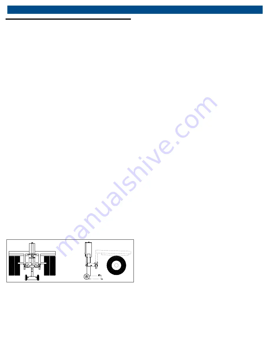
The  proper  lift  points  on  an  ICC  bumper  are  directly 
beneath the vehicle structure members (Fig.


4), which 

connect  with  the  frame  and  are  approximately  34 
inches  apart  in  width.  Slowly  raise  the  lift  frame  to 
engage  the  bottom  of  the  bumper.  Raise  the  rear  of 
the trailer to the desired height and then install vehicle 
stands  of  the  proper  capacity  to  support  the  trailer. 
Once  the  stands  are  in  place,  lower  the  trailer  onto 
them  and  then  remove  the  lift  from  the  work  area. 
Follow  the  instructions  for  lowering  when  work  is 
completed. 

Fig. 4: Lifting trailer 


Summary of Contents for CAL-10

Page 1: ...MAHLE CAL 10 EN Operation Manual Vehicle Air Lift...

Page 2: ...Y PERSON WHO OPERATES THIS EQUIPMENT NEEDS TO KNOW AND UNDERSTAND ALL OF THE INFORMATION IN THIS MANUAL FAILURE TO DO SO COULD RESULT IN SERIOUS INJURY OR DEATH READ THIS MANUAL CAREFULLY AND RETAIN F...

Page 3: ...entification 7 7 Operation 8 7 1 Preparing to lift 8 7 2 Operating the air valve to raise a load 8 7 3 Function and purpose of lift 9 7 4 Moving and positioning the lift 9 7 5 Adjusting saddle horn he...

Page 4: ...ssible If this warning is not heeded it may result in possible serious injury and or property damage or death Use the jack to raise one end of a vehicle or trailer This jack is designed to for lifting...

Page 5: ...ay Manufacturing name Please contact MAHLE Service Solutions customer service at 800 468 2321 or tech mss us mahle com with any comments or questions 3 Symbols Use 3 1 Signal words Signal words call a...

Page 6: ...ound the equipment know of the risks associated with its use Personnel involved in the use and operation of this equipment shall be careful competent trained and qualified in the safe operation of the...

Page 7: ...ion 6 1 Component identification Fig 1 Side view 1 Base 2 Air cylinder 3 Cylinder head plate 4 Pneumatic wheel 5 Swivel caster Fig 2 Rear view 1 Valve handle 2 Valve cover 3 Handle grip 4 Downstpp rel...

Page 8: ...ns cannot be met move the vehicle and jack to an area where the lift can be performed safely 6 Chock the vehicle s wheels When raising a vehicle from one end always chock the wheels that will remain o...

Page 9: ...t ever does fall for whatever reason get out of the way immediately NEVER try to catch the lift if it falls backwards 7 5 Adjusting saddle horn height On occasion it may be necessary to adjust the hei...

Page 10: ...ifting location Roll the lift into place make sure it is centered in the trailer and bumper Make sure that the lift saddles on the lift frame fully engage cradle the bottom of the bumper and that the...

Page 11: ...the lift must be removed for service and returned to the manufacturer for servicing This unit is equipped with a non serviceable vertical restraint and must be returned to the factory for repair Cont...

Page 12: ...o the pipe nipple using pipe thread sealant on the threads of the nipple 9 Troubleshooting This section is a list of potential problems and solutions If the solution listed fails to correct the proble...

Page 13: ...CAL 10 13 en Maintenance Chart 11 Maintenance Chart Action Date Details Person responsible Receiving inspection...

Page 14: ...en 14 CAL 10 Maintenance Chart Action Date Details Person responsible...

Page 15: ...CAL 10 15 en Notes 12 Notes...

Page 16: ...en 16 TSL 50 670 90748 MAHLE Aftermarket Inc 10 Innovation Drive York PA 17402 U S A Phone 800 468 2321 Fax 717 755 8304 E mail tech mss us mahle com www servicesolutions mahle com...

Reviews: