


32
BA053101-en
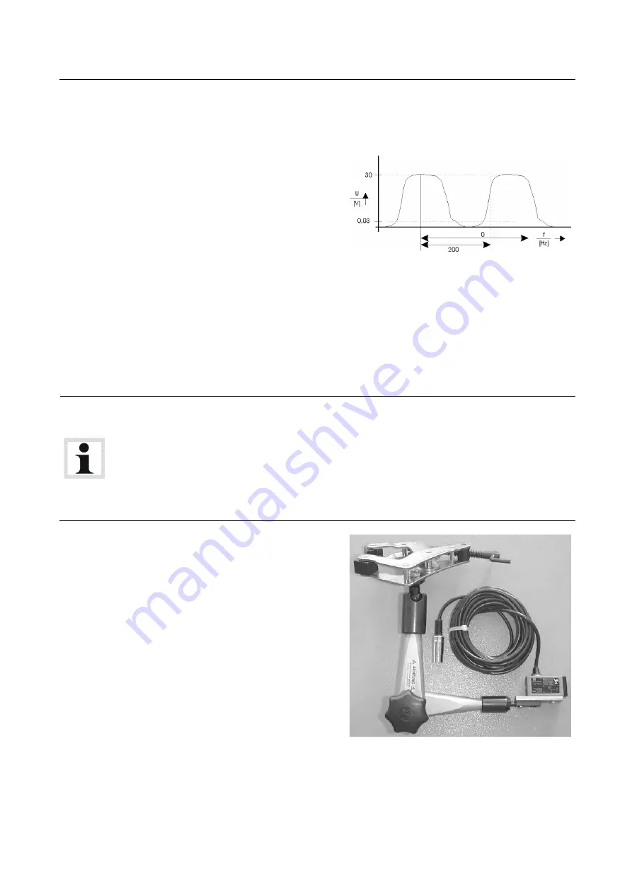
TDC Sensor
The TDC sensor is always manufacturer-specific, i.e. depending on the vehicle manufacturer the
corresponding diagnostic plug is used for the RPM signal pick up.
The TDC sensor offers an extremely accurate
RPM measurement.
Once f
max
is reached, an RPM of 12000
rot/min
-1
is displayed.
The level must be between 30 mV and 30 V
so that an RPM pulse is recognized
Attachment:
•
Position (A) or (B) on the interface box.
Light Barrier
The light barrier is used when no direct way of determining the RPM at the engine is possible. The
transmission ratio to the engine RPM must be 1:1. If the light barrier is attached to the cardan
shaft, the transmission ratio must be between 0.5 and 2. The light barrier must be positioned in
such a way that via a reflector which is attached either to the vibration absorber, drive belt, or
cardan shaft, the RPM can be picked up free of any interference (no vibration influence etc.).
Notes on adjusting the engine rpm via the light barrier
When making adjustments in the lower rpm range (drive shaft rpm < 800), we recommend using
two reflectors in order to double the number of impulses generated.
When doing so, please remember the following:
•
The reflectors must be systematically placed around the engine, exactly opposite one another.
Prominent points on the engine housing can be used to position the reflectors.
•
When entering the gear ratio you must also double the previous value.
Attachment:
Position (A) or (B) on the interface box.
Driving Trial
If none of the above mentioned alternatives is available for determining an RPM measurement, a
driving trial can be used to do the same. The RPM is converted from the dyno roller speed.


