42
REASSEMBLY OF PUMP COMPONENTS
SHAFT AND BEARINGS
Clean the housing and components with an appropriate cleaning solvent and use compressed air to dry components.
If bearings need replacement, remove the outboard (drive end) bearing retaining ring and use an appropriate bearing
puller to remove bearings from shaft. Inspect shaft and replace if distorted, nicked, or scratched beyond repair.
If bearings are to be replaced, then the bearings may be heated to 250ºF (121ºC) for ease of installation. An induction
heater, electric oven, or hot plate may be used to heat the bearings. Never use direct flame to heat bearings.
After heating the bearings, slide the bearings on the appropriate shaft end. When installing the bearings onto the
shaft, only press against the inner bearing race. The inboard bearing should be installed with the shielded side toward
the impeller. The outboard bearing should have the integral retaining ring on the bearing outside diameter toward
the drive end of the shaft.
After installation of bearing, ensure that bearings are tight against shaft shoulders. Secure the outboard bearing on
the shaft with the bearing retaining ring. Slide the shaft and assembled bearings into the bearing housing until the
retaining ring contacts the bearing housing.
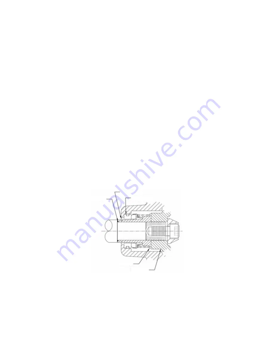
SEAL INSTALLATION
A new seal assembly should be installed any time the old seal is removed. The wear pattern on the old seal can
cause premature failure if reused. Thoroughly clean the shaft where the mechanical seal will be installed, and the
seat of the seal housing. Place the sleeve O-ring over the shaft, past the threads and up against the shaft shoulder.
Lubricate the stationary seat bore and stationary seat O-ring with P-80, 30 wt. motor oil, or liquid dish detergent and
a little water.
DO NOT USE GREASE OR SILICONE LUBRICANTS
.
Remove the plastic, U-shaped seal-setting spacer from the cartridge seal assembly. Carefully slide the cartridge
seal assembly over the shaft, with the stationary seat towards the bore. By hand only, carefully press on the flanged
end of the cartridge seal sleeve until the stationary seat bottoms in the stationary seat bore. Install impeller according
to instructions.
IMPELLER
The shaft and impeller threads must be completely clean before re-installing the impeller. Apply anti-seize compound
to the external shaft threads.
DO NOT USE ANTI-SEIZE COMPOUNDS ON THE LOCKSCREW THREADS.
Screw
the impeller onto the shaft until tight. A clearance of .025 to .035 in (.63 to .89 mm) between the impeller and the
seal plate is recommended for optimum pump efficiency.
Measure this clearance between the impeller and the rotating assembly with the rotating assembly sitting on the
impeller with the shaft oriented vertically. Add or remove impeller adjusting shims as required to achieve the correct
clearance. Apply Loctite 2760®, or equivalent thread locking compound, to impeller screw and install impeller washer
and screw.
O-ring
Snap Ring
Seal Seat
Sleeve
Impeller


