©
2014 Magnum Energy, Inc.
Page 85
Using an AGS Module: Troubleshooting
7.3
AGS Troubleshooting using the ME-ARC
This section assists you in using your ME-ARC remote to identify a fault and to resolve an abnor-
mal operational condition detected within your AGS system.
7.3.1
AGS Fault Message Screen
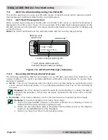
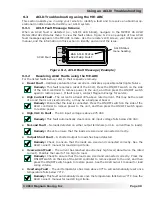
When an AGS fault is detected, the ME-ARC’s red FAULT LED comes on and the fault status is
displayed on the LCD screen. Figure 7-6 is an example of how AGS fault messages appear on the
ME-ARC remote. Use the remote’s LCD screen and the information in this section to identify and
correct the issue.
Note:
The FAULT LED blinks and the fault alternates with the inverter/charger status.
Blinking (red)
FAULT LED
** AGS status alternates with
inverter/charger status (scrolling).
AGS Status**
Inverter/Charger Setting/Info
FAULT
PWR
CHG
INV
Fault Temp
Settings/Info..
Figure 7-6, AGS Fault Message (Example)
7.3.2
Resolving AGS Operational Statuses
The following operational statuses can display on your ME-ARC, and some may indicate an ab-
normal condition. This section provides additional information and assistance to resolve these
statuses (if needed).
• AC
In
– This is a normal status when the input to the inverter/charger is connected to an AC
source such as utility/grid power, or to an alternate generator that may not be controlled by
the AGS.
Remedy:
The AC In status prevents the AGS from autostarting. To enable the AGS to
autostart the generator, remove any AC power connected to the input of the inverter/
charger.
• No
Comm
– If an AGS is installed, use the information below to determine the remedy.
Remedy:
If an AGS is installed, then follow these steps:
1. Ensure the green READY indicator on the AGS controller is on (blinking or solid) to
indicate that the AGS controller is getting power.
2. Ensure the communications cable is connected from the Network port on the Magnum
inverter to the NETWORK port on the ME-AGS-N.
3. Ensure you have the correct communications cable.

