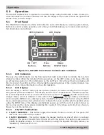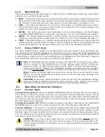
©
2014 Magnum Energy, Inc.
Page 47
Operation
5.2.2 Charger
Mode
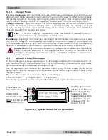
Turning the charger on:
The charge mode is automatically activated and begins when accept-
able AC power (utility/generator) is connected to the input of the inverter. When in charge mode,
the display may show:
Charging
,
Bulk Charging
,
Absorb Charging
,
Float Charging
,
Full Charge
,
Silent
,
Charger Standby
,
Force Float
,
Equalizing, Load Support VDC,
and
Load Support AAC
.
Charger Standby
– While the charger is actively charging, press the ON/OFF CHARGER button
to switch the charger to Charger Standby. While in Charger Standby, the incoming AC is still
available on the inverter’s output, but the charger is not allowed to charge. The LCD displays
“
Charger Standby
” and the CHG LED
fl
ashes.
Info:
To resume charging, momentarily press the ON/OFF CHARGER button or
disconnect/reconnect AC power to the inverter’s input.
Equalizing
– Equalizing is a “controlled overcharge” performed after the batteries have been
fully charged. It helps to mix the battery electrolyte (to reverse the buildup of strati
fi
cation) and
to remove sulfates that may have built up on the plates. These conditions if left unchecked, re-
duce the overall capacity of the battery. To enable the Equalization charge, see page 49.
WARNING:
Do not perform an Equalization charge without reading and following all
safety precautions pertaining to charging/equalization as noted in this manual and
provided by the battery manufacturer, and any equalization information in the inverter
owner’s manual.
5.3
System Status Messages
A status message may be an operational or fault message indicating the inverter/charger’s cur-
rent operating status. This section will cover the inverter/charger’s operating and fault modes,
and the available status messages under each mode.
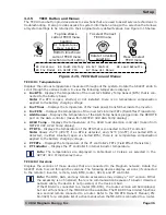
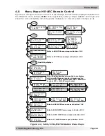
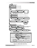
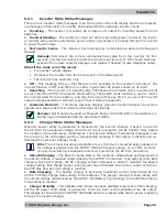
Use the displayed status message and the status LEDs on your ME-ARC remote (Figure 5-2) to
determine the inverter/charger’s current operating status, and to help troubleshoot the system
if a fault occurs.
There are three modes of operation for the inverter/charger:
• Inverter mode • Charger mode • Fault mode
Refer to the appropriate section to locate information on any particular status message.
FAULT
PWR
CHG
INV
Status Message
Settings/Info...
FAULT LED on:
See Section 5.3.4
CHG LED on:
See Section 5.3.2
Only INV LED on:
See Section 5.3.1
See the appropriate
section to determine
the meaning of the
message. If the
message scrolls with
a secondary screen
message, refer to
Section 5.3.3.
Figure 5-2, System Status Screen (Example)

