background image

Flex 8EX EU System Instruction Manual 

March 2012 

35 of 37 

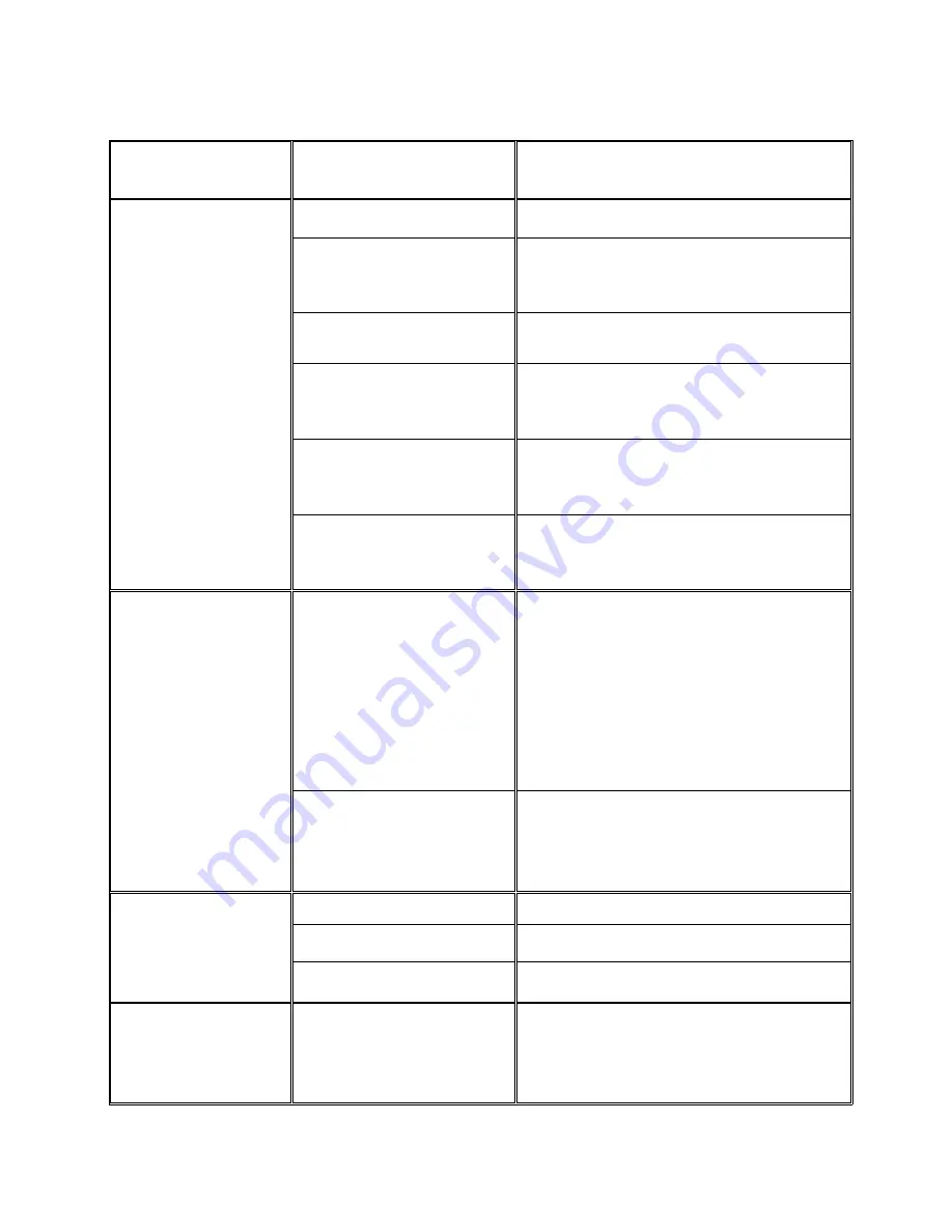
C. Troubleshooting Tips 


Problems Possible 

Reasons 

Suggestions 

No response when 

transmitter push  

button is pressed 

(Improper startup & 

settings)  

Transmitter low battery power 

Check the transmitter battery level. 

Emergency stop button  

activated prior to startup 

Prior to turning on the transmitter power switch 

make sure that the red emergency stop button 

is elevated.  

Transmitter push button 

functions locked 

Initiate the Start command by rotating the 

power key-switch to START position. 

Incorrect system RF channel 

Check and make sure that the transmitter 

handset and receiver unit both have the same 

channel. 

Incorrect system serial 

number/ID code 

Check and make sure that the transmitter 

handset and receiver unit both have the same 

serial number/ID code. 

System out of range 

Make sure that the startup procedure is  

initiated within 100 meters (300 feet) from the 

receiver location. 

No response when 

transmitter push  

button is pressed 

(Damaged hardware) 

Defective transmitting and 

receiving module 

Check the SQ display on the face of the 

receiver unit. If it does not light up when the 

push button is pressed then either the 

transmitting or receiving module is defective. 

First replace the transmitting module. If SQ 

display is still not lit when the push button is 

pressed then go ahead and replace the 

receiving module. 

Defective encoder  

board or decoder module 

If still no response, then replace the transmitter 

encoder board. If still  

doesn’t work then the decoder module  

is defective.   

No AC power to  

the receiver 

Incorrect input voltage 

Make sure the source voltage is set correctly. 

Blown fuse 

Check for any blown fuse. 

Incorrect wiring 

Check input voltage connection. 

Outputs do not 

correspond to  

transmitter  

Incorrect output connection 

Check the system wiring again. Please refer to 

the output contact diagram inside this manual 

or on the receiver cover. 


Summary of Contents for Enrange Flex EX

Page 1: ...Flex 8EX EU System Radio Control Equipment Instruction Manual 191 00193 0003 R0 March 2012 Copyright 2012 Magnetek Material Handling...

Page 2: ...needs modification or service please contact one of our representatives using the information below U S Service Information For questions regarding service or technical information contact 1 866 MAG...

Page 3: ...o Scanning Settings 21 4 Dip Switch Settings 22 5 Jumper Settings 24 6 I CHIP Programming Port 25 7 Voltage Settings 25 5 System Channels Table 26 6 Receiver Installation 27 A Output Relay Contact Dia...

Page 4: ...ver channels Over one million unique ID codes 20bit Each and every Flex system has its own unique ID codes and serial number never repeats Advanced controls The Flex system utilizes advanced microproc...

Page 5: ...ansmitter for any signs of low battery power refer to page 33 4 Check the Status LED on the transmitter for any signs of irregularities refer to page 33 5 The crane limit switches should be checked pr...

Page 6: ...andard Push Button Configuration Fig 01 Fig 02 1 Emergency Stop Button 9 Push Button 5 2 Removable Power Key Switch 10 Push Button 7 3 Push Button 2 11 Strap Ring 4 Push Button 4 12 System Information...

Page 7: ...March 2012 5 of 37 2 Internal Illustration Fig 03 Fig 04 1 Encoder Board 6 I CHIP 2 Arial Antenna 7 Function Dip Switch 3 Transmitting Module 8 Channel Dip Switch 4 Status LED Display 9 Battery Conta...

Page 8: ...2012 6 of 37 B Receiver Unit 1 External Illustration Fig 05 1 Shock Mount 6 COM LED Display 2 Optional External Antenna BNC Jack 7 Output Contact Diagram 3 Power LED Display 8 System Information 4 Sta...

Page 9: ...Flex 8EX EU System Instruction Manual March 2012 7 of 37 2 Internal Illustration Fig 06 1 AC Line Filter 4 Decoder Module 2 Power Transformer 5 Output Relay Board 3 Receiving Module...

Page 10: ...sed for channel programming refer to Fig 08 below The system channels table located on page 26 illustrates which dip switch setting corresponds to which channel Once the transmitter channel is altered...

Page 11: ...ill cease transmission thus temporarily disconnecting the receiver MAIN After the push button is released the transmitter will continue to transmit neutral signals to the receiver for up to three 3 mi...

Page 12: ...ansmitter encoder board refer to Fig 09 below The LED 1 through LED 4 shown inside the shaded box see below illustrates which LED on the transmitter will light up when the designated push button PB5 P...

Page 13: ...al Normal C 1 2 Normal 9 00110010 Normal Normal D 1 2 Normal 10 00110011 Normal Normal Normal A 3 4 11 00110100 Normal Normal Normal B 3 4 12 00110101 Normal Normal Normal C 3 4 13 00110110 Normal Nor...

Page 14: ...ase refer to JP4 and JP5 jumpers setting on page 24 With inline push button configurations PB1 PB2 still corresponds to output relay K1 K4 PB3 PB4 corresponds to relay K5 K8 etc Fig 10 DIP PB5 PB6 PB7...

Page 15: ...al Normal C 1 2 Normal 32 01110110 Normal Normal D 1 2 Normal 33 00110011 Normal Normal Normal A 3 4 34 00110100 Normal Normal Normal B 3 4 35 00110101 Normal Normal Normal C 3 4 36 00110110 Normal No...

Page 16: ...b Select a new channel by pressing PB1 and PB2 on the transmitter Press PB1 to increment the units 1 and PB2 to increment the tens 10 Examples Pressing PB2 two times and then PB1 four times will give...

Page 17: ...is time fast orange blinks are displayed on the Status LED telling you to reconfirm the 4 digit security code you have just entered A green light will appear once you have re entered the same 4 digit...

Page 18: ...ll operate according to the channel and push button configurations set on these two dip switches not the ones stored inside the I CHIP Every time the settings on these two dip switches are changed the...

Page 19: ...the receiver module refer to Fig 12 above only the first six 6 positions are used for channel programming refer to Fig 13 below The system channels table located on page 26 illustrates which dip swit...

Page 20: ...utput relay 2 Four 4 output relays per motion separate 1st and 2nd speed output relays Output relays with Forward 1st speed F1 Reverse 1st speed R1 Forward 2nd speed F2 and Reverse 2nd speed R2 Forwar...

Page 21: ...are closed refer to page 22 on how to set to this function Forward 1 st speed push button pressed Forward 2 nd speed push button pressed c ON OFF Push Button Function The user can set any of the two a...

Page 22: ...ow to set to this function This type of contact is usually applied to external applications such as horns or buzzers h Toggled Contact When the push button is released the output relay that correspond...

Page 23: ...hand since there are only 62 available channels on the Flex system the system preset at channel 62 is ineffective because the 2nd transmitter can not be set to Ch 63 If your system is preset at Ch 62...

Page 24: ...ns of Relays Used 0000000 Normal single speed only F2 R2 relays not used 2 0000001 Closed Closed Relay Action at 2nd Speed separate 2nd speed relay 4 0000010 Closed Closed Relay Action at 2nd Speed sh...

Page 25: ...r key switch at START position and then press the intended push button at the same time to activate the output relay E 1 110 Pitch Catch F 1 111 Auxiliary Stop Example 1 Left button set to function co...

Page 26: ...te the receiver MAIN JP3 Inserted After 1 or 3 minutes of transmitter inactivity MAIN deactivated rotate the transmitter power key switch to START position to reactivate the receiver MAIN JP4 Blank JP...

Page 27: ...t reinsert the I CHIP one more time On the other hand if you wish to transfer system information from the I CHIP to the receiver then you must first insert JP6 jumper prior to inserting the I CHIP the...

Page 28: ...34 075MHZ 101100 13 433 300MHZ 001101 45 434 100MHZ 101101 14 433 325MHZ 001110 46 434 125MHZ 101110 15 433 350MHZ 001111 47 434 150MHZ 101111 16 433 375MHZ 010000 48 434 175MHZ 110000 17 433 400MHZ 0...

Page 29: ...ation please refer to pages 18 22 For the 4 relay closed closed and 4 relay opened closed relay configuration please refer to pages 18 22 For different voltage settings please refer to page 25 For F9...

Page 30: ...ior to installation 4 Make sure the power source to the receiver is set correctly 5 Switch off the main power source to the crane or equipment prior to installation C Step by Step Installation Fig 19...

Page 31: ...Drill two holes 10mm in diameter on the control panel or location where the receiver is to be installed refer to Fig 19 on page 28 7 Make sure the two bolts are tightened after installation 8 For sys...

Page 32: ...kwise to the On position c After turning on the transmitter power check the Status LED on the transmitter handset for any sign of system irregularities refer to Status Light Indicators Warnings on pag...

Page 33: ...e transmitter to resume operation depending on JP3 setting on page 24 If this 1 minute inactivity time is not sufficient for your application you can also extend this inactivity time from 1 minute up...

Page 34: ...witch to the Start position and hold it there for up to 1 minute Within this 1 minute period the receiver will search channel 01 channel 62 and lock onto the newly selected transmitter channel automat...

Page 35: ...the transmitter power 4 No light displayed When a defective push button condition occurs 2 red blinks type 3 above find out which push button is defective by pressing all the push buttons on the trans...

Page 36: ...ed Receiver under voltage LV output relay activated 6 No light displayed Decoding microprocessor is defective 3 Receiver SQ Light Indication Type Display Type Red Indication 1 Fast blinks Transmission...

Page 37: ...rtup procedure is initiated within 100 meters 300 feet from the receiver location No response when transmitter push button is pressed Damaged hardware Defective transmitting and receiving module Check...

Page 38: ...ing Receiver Sensitivity 116dBm Antenna Impedance 50 ohms Responding Time 40 Milliseconds average Transmitting Power 0 3mW Enclosure Type NEMA 4X Enclosure Rating IP 66 Output Contact Rating 250V 10 A...

Page 39: ...Flex 8EX EU System Instruction Manual March 2012 37 of 37...

Reviews: