32
(E)
MG10-P1 / MG10-P2
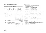
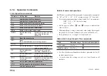
No. I/O
Pin
Description
7
–
Output Common Output signal common pin
(P1:
−
COM/P2: +COM)
6
O
Alarm
Alarm output
5
–
Input Common
Input signal common pin
(P1: +COM/P2:
−
COM)
4
I
Start/latch input
When the start function is selected
as the input setting: the peak value
updating starts as soon as the
input signal is supplied;
when the latch function is selected:
while the input signal is supplied,
the value is compared with the
current value and the comparator’s
result is latched.
3
I
Pause input
While the input signal is supplied,
the updating of the peak value is
temporarily stopped.
2
I
RS trigger input
The data of all the channels at the
time when the input signal is
supplied is latched and output from
the RS-232C port.
When a link connection is used to
connect more than one unit, all
data from the input unit and units
connected below it is output from
the RS-232C port.
1
I
Reset input
All the channels are reset.
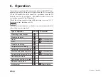
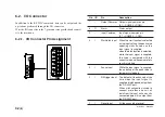
6-2. I/O Connector
In addition to the RS-232C command, data can be output and the
operations performed through the I/O connector.
Wire the I/O connector to the 7-pin connector provided and connect
it to the main unit.
6-2-1. I/O Connector Pin Assignment
Summary of Contents for MG10-P1
Page 3: ...J 1 MG10 P1 MG10 P2...
Page 4: ...2 J MG10 P1 MG10 P2 DC AC...
Page 6: ...MG10 P1 MG10 P2 ii J Microsoft Windows Windows 7 35 8 36 8 1 36 8 2 37 8 3 37 9 38...
Page 9: ...MG10 P1 MG10 P2 J 3 1 3 BCD DG DT DL DK PLC 16 RS 232C...
Page 10: ...MG10 P1 MG10 P2 4 J 2 6 7 4 5 8 2 9 10 11 12 13 14 1 3...
Page 12: ...MG10 P1 MG10 P2 6 J 3 3 1 16 1 2...
Page 13: ...MG10 P1 MG10 P2 J 7 3 4 2 3 1 1 4 3 2 I F I F 1 1...
Page 14: ...MG10 P1 MG10 P2 8 J 2 I F I F 3 1 3...
Page 15: ...MG10 P1 MG10 P2 J 9 2 DIN DIN DIN 3 3 DIN DIN DIN 35 mm 1 DIN...
Page 16: ...MG10 P1 MG10 P2 10 J 3 5 1 3 I O 3 GND 2 Vin DC 12 V 24 V 1 FG 2 3 3 4 1...
Page 17: ...MG10 P1 MG10 P2 J 11 3 6 1 LZ61 CE08 RS 232C I F 3 7 1 RS 232C DZ252 RS 232C...
Page 19: ...MG10 P1 MG10 P2 J 13 4 2 3 DK 1 1 mm 2 1 mm 3...
Page 20: ...MG10 P1 MG10 P2 14 J 4 2 5 P P 4 RS 232C SETUP P CLOSE 1 mm RS 232C 1 4 2 4 0...
Page 21: ...MG10 P1 MG10 P2 J 15 4 2 6 RS 232C MG30 B BCD 4 RS 232 NG U GO G GO G GO G NG L...
Page 22: ...MG10 P1 MG10 P2 16 J ON P P OFF 4 2 7...
Page 24: ...MG10 P1 MG10 P2 18 J 5 2 5 2 1 1 0 F...
Page 28: ...MG10 P1 MG10 P2 22 J 7 ASCII ASCII ASCII OK 8 R...
Page 32: ...MG10 P1 MG10 P2 26 J 6 RS 232C I O I F I F I F 4 2 3 OFF RS 232C I O...
Page 40: ...MG10 P1 MG10 P2 34 J 6 2 3 RS 232C MIN 25 ms MIN 1 ms RS RS MIN 2 ms MAX 2 ms MIN 2 ms...
Page 44: ...MG10 P1 MG10 P2 38 J q 12 V 24 V w RS 232C MG10 MG10 e MG10 9 r MG10 t...
Page 52: ...4 E MG10 P1 MG10 P2 6 7 4 5 8 2 9 10 11 12 13 14 1 3 2 Name and Function of Each Part...
Page 94: ...4 G MG10 P1 MG10 P2 6 7 4 5 8 2 9 10 11 12 13 14 1 3 2 Teilebezeichnungen und Funktionen...


