(E)
5
MG10-P1 / MG10-P2
i
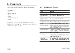
RS-232C connector
Connects the unit to a computer or PLC host unit.
The connector at the end of the RS-232C cable (DZ252) sold
separately is connected here.
o
LINK IN connector
When using the link connection for the units, the link cable
(LZ61) is used to connect this connector with the LINK OUT
connector of a higher order unit’s main module.
!0
LINK OUT connector
When using the link connection for the units, the link cable
(LZ61) is used to connect this connector with the LINK IN
connector of a lower order unit’s main module.
!1
Counter module connector
This is connected to the counter module.
!2
I/F module connector
This is connected to the I/F module.
!3
Slide locks
Secures a module which has been connected.
!4
DIN rail anchoring lever
Secures the main unit to the DIN rails.
q
POWER lamp
Lights green when the power is on and the unit is ready for
operation.
w
Alarm lamp
Lights red when any counter module of the unit enters the alarm
status.
e
HOLD lamp
Lights orange when the hold function (in which current value
output data is latched or the peak value data updating is stopped)
is activated in any counter module of the unit.
r
Unit number setting switch
Sets the unit number to a number from 0 to F.
t
RS-232C communication setting switch
Sets the RS-232C communication specifications.
y
I/O connector
Connects the I/O connector of a PLC or other device and
controls it.
u
Power input socket
The external power supply (DC
+
12 V to 24 V) is connected
here.
Summary of Contents for MG10-P1
Page 3: ...J 1 MG10 P1 MG10 P2...
Page 4: ...2 J MG10 P1 MG10 P2 DC AC...
Page 6: ...MG10 P1 MG10 P2 ii J Microsoft Windows Windows 7 35 8 36 8 1 36 8 2 37 8 3 37 9 38...
Page 9: ...MG10 P1 MG10 P2 J 3 1 3 BCD DG DT DL DK PLC 16 RS 232C...
Page 10: ...MG10 P1 MG10 P2 4 J 2 6 7 4 5 8 2 9 10 11 12 13 14 1 3...
Page 12: ...MG10 P1 MG10 P2 6 J 3 3 1 16 1 2...
Page 13: ...MG10 P1 MG10 P2 J 7 3 4 2 3 1 1 4 3 2 I F I F 1 1...
Page 14: ...MG10 P1 MG10 P2 8 J 2 I F I F 3 1 3...
Page 15: ...MG10 P1 MG10 P2 J 9 2 DIN DIN DIN 3 3 DIN DIN DIN 35 mm 1 DIN...
Page 16: ...MG10 P1 MG10 P2 10 J 3 5 1 3 I O 3 GND 2 Vin DC 12 V 24 V 1 FG 2 3 3 4 1...
Page 17: ...MG10 P1 MG10 P2 J 11 3 6 1 LZ61 CE08 RS 232C I F 3 7 1 RS 232C DZ252 RS 232C...
Page 19: ...MG10 P1 MG10 P2 J 13 4 2 3 DK 1 1 mm 2 1 mm 3...
Page 20: ...MG10 P1 MG10 P2 14 J 4 2 5 P P 4 RS 232C SETUP P CLOSE 1 mm RS 232C 1 4 2 4 0...
Page 21: ...MG10 P1 MG10 P2 J 15 4 2 6 RS 232C MG30 B BCD 4 RS 232 NG U GO G GO G GO G NG L...
Page 22: ...MG10 P1 MG10 P2 16 J ON P P OFF 4 2 7...
Page 24: ...MG10 P1 MG10 P2 18 J 5 2 5 2 1 1 0 F...
Page 28: ...MG10 P1 MG10 P2 22 J 7 ASCII ASCII ASCII OK 8 R...
Page 32: ...MG10 P1 MG10 P2 26 J 6 RS 232C I O I F I F I F 4 2 3 OFF RS 232C I O...
Page 40: ...MG10 P1 MG10 P2 34 J 6 2 3 RS 232C MIN 25 ms MIN 1 ms RS RS MIN 2 ms MAX 2 ms MIN 2 ms...
Page 44: ...MG10 P1 MG10 P2 38 J q 12 V 24 V w RS 232C MG10 MG10 e MG10 9 r MG10 t...
Page 52: ...4 E MG10 P1 MG10 P2 6 7 4 5 8 2 9 10 11 12 13 14 1 3 2 Name and Function of Each Part...
Page 94: ...4 G MG10 P1 MG10 P2 6 7 4 5 8 2 9 10 11 12 13 14 1 3 2 Teilebezeichnungen und Funktionen...

