6
(E)
MG10-P1 / MG10-P2
3. Connections and Installation
3-1. Connecting the Counter Modules
The type of counter module that can be connected is not limited.
Counter modules can be mixed and used in accordance with the
application. Up to 16 counter modules can be connected.
1
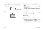
Remove the rubber cover installed over the counter module
connector on the right side panel of the main module.
2
Set the slide lock position as shown in the figure.
Install the first counter module into the main module so that
the counter module connector is aligned properly.
Summary of Contents for MG10-P1
Page 3: ...J 1 MG10 P1 MG10 P2...
Page 4: ...2 J MG10 P1 MG10 P2 DC AC...
Page 6: ...MG10 P1 MG10 P2 ii J Microsoft Windows Windows 7 35 8 36 8 1 36 8 2 37 8 3 37 9 38...
Page 9: ...MG10 P1 MG10 P2 J 3 1 3 BCD DG DT DL DK PLC 16 RS 232C...
Page 10: ...MG10 P1 MG10 P2 4 J 2 6 7 4 5 8 2 9 10 11 12 13 14 1 3...
Page 12: ...MG10 P1 MG10 P2 6 J 3 3 1 16 1 2...
Page 13: ...MG10 P1 MG10 P2 J 7 3 4 2 3 1 1 4 3 2 I F I F 1 1...
Page 14: ...MG10 P1 MG10 P2 8 J 2 I F I F 3 1 3...
Page 15: ...MG10 P1 MG10 P2 J 9 2 DIN DIN DIN 3 3 DIN DIN DIN 35 mm 1 DIN...
Page 16: ...MG10 P1 MG10 P2 10 J 3 5 1 3 I O 3 GND 2 Vin DC 12 V 24 V 1 FG 2 3 3 4 1...
Page 17: ...MG10 P1 MG10 P2 J 11 3 6 1 LZ61 CE08 RS 232C I F 3 7 1 RS 232C DZ252 RS 232C...
Page 19: ...MG10 P1 MG10 P2 J 13 4 2 3 DK 1 1 mm 2 1 mm 3...
Page 20: ...MG10 P1 MG10 P2 14 J 4 2 5 P P 4 RS 232C SETUP P CLOSE 1 mm RS 232C 1 4 2 4 0...
Page 21: ...MG10 P1 MG10 P2 J 15 4 2 6 RS 232C MG30 B BCD 4 RS 232 NG U GO G GO G GO G NG L...
Page 22: ...MG10 P1 MG10 P2 16 J ON P P OFF 4 2 7...
Page 24: ...MG10 P1 MG10 P2 18 J 5 2 5 2 1 1 0 F...
Page 28: ...MG10 P1 MG10 P2 22 J 7 ASCII ASCII ASCII OK 8 R...
Page 32: ...MG10 P1 MG10 P2 26 J 6 RS 232C I O I F I F I F 4 2 3 OFF RS 232C I O...
Page 40: ...MG10 P1 MG10 P2 34 J 6 2 3 RS 232C MIN 25 ms MIN 1 ms RS RS MIN 2 ms MAX 2 ms MIN 2 ms...
Page 44: ...MG10 P1 MG10 P2 38 J q 12 V 24 V w RS 232C MG10 MG10 e MG10 9 r MG10 t...
Page 52: ...4 E MG10 P1 MG10 P2 6 7 4 5 8 2 9 10 11 12 13 14 1 3 2 Name and Function of Each Part...
Page 94: ...4 G MG10 P1 MG10 P2 6 7 4 5 8 2 9 10 11 12 13 14 1 3 2 Teilebezeichnungen und Funktionen...


