Magenta Mondo III Matrix Installation & Setup Manual Download Page 3


FEDERAL COMMUNICATIONS COMMISSION AND INDUSTRY CANADA 
RADIO FREQUENCY INTERFERENCE STATEMENTS 


This device complies with part 15 of the FCC Rules. Operation is subject to the following two conditions:  

1) This 

device may not cause harmful interference, and  
 

(2) this device must accept any interference received, including interference that may cause 


     undesired operation. 


 This equipment has been tested and found to comply with the limits for a Class A digital device, pursuant to part 15 
of the FCC Rules. These limits are designed to provide reasonable protection against harmful interference when the 
equipment is operated in a commercial environment. This equipment generates, uses, and can radiate radio 
frequency energy and, if not installed and used in accordance with the instruction manual, may cause harmful 
interference to radio communications. Operation of this equipment in a residential area is likely to cause harmful 
interference in which case the user will be required to correct the interference at his own expense. 


Canada (ICES-003) notice: This Class A digital apparatus complies with Canadian ICES-003. 
Cet appareil numerique de la classe A est conforme a la norme NMB-003 du Canada. 

 
EUROPEAN UNION DECLARATION OF CONFORMITY 


Warning: This is a Class A product. In a domestic environment this product may cause radio 
interference in which case the user may be required to take adequate measures. 
 
Magenta Research (New Milford CT USA) declares under our sole responsibility that the product 

Mondo III System 

to which this declaration relates is in conformity with the following standard(s) or other normative documents: 
 

EN 55022:1998/A1:2000/A2:2003 Class A ITE emissions requirements (EU AS/NZS). 


EN61000-3-2:2006 Limits for harmonic current emissions (equipment input current up to  


  and including 16A per phase). 


EN 61000-3-3:1995/A1:2001/A2:2005 Limitation of voltage fluctuations and flicker on low- 


  voltage supply systems for equipment with rated current up to and including 16A. 


EN60950-1:2006 Safety for Information Technology Equipment 


EN55024:1998/A1:2001/A2:2003 Immunity for ITE 


SAFETY WARNING 


Installation • 

This equipment is to be installed in a restricted access location. 


Connection • 

Not for direct connection to Telecommunication Network Circuitry (TNV) 


Power sources • 

This equipment should be operated only from the power source indicated on the product. This 

equipment is intended to be used with a main power system with a grounded (neutral) conductor. The 
third (grounding) pin is a safety feature, do not attempt to bypass or disable it. 
This equipment can be powered from redundant power sources. Disconnect all power sources before servicing. 


Power disconnection • 

To remove power from the equipment safely, remove all power cords from the rear of 

the equipment, or from the power source receptacle (wall plug). Note that this equipment has multiple power inputs. 


Power cord protection • 

Power cords should be routed so that they are not likely to be stepped on or pinched by 

items placed upon or against them. 


Servicing • 

Refer all servicing to qualified service personnel. There are no user-serviceable parts inside. To 

prevent the risk of shock, do not attempt to service this equipment yourself because opening or removing 
covers may expose you to dangerous voltage or other hazards. 


Slots and openings • 

If the equipment has slots or holes in the enclosure, these are provided to prevent 

overheating of sensitive components inside. These openings must never be blocked by other objects. 


Lithium battery • 

There is a danger of explosion if battery is incorrectly replaced. Replace it only with the 

same or equivalent type recommended by the manufacturer. Dispose of used batteries according to local laws. 
The battery stores configuration information in the event of a power failure. Contact manufacturer for battery 
replacement procedures. Battery is not intended to be a user serviceable part


FCC/IC RFI STATEMENTS, EU DECLARATION OF CONFORMIT, SAFETY WARNING. 

Summary of Contents for Mondo III Matrix

Page 1: ...1 Mondo III Matrix Installation Setup Guide...

Page 2: ...either express or implied with respect to this software or documentation including their quality performance merchantability or fitness for a particular purpose As a result this software or documentat...

Page 3: ...ations and flicker on low voltage supply systems for equipment with rated current up to and including 16A EN60950 1 2006 Safety for Information Technology Equipment EN55024 1998 A1 2001 A2 2003 Immuni...

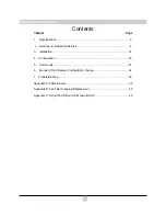
Page 4: ...rview Design Guidelines 4 3 Installation 14 4 Configuration 18 5 Commands 21 6 Mondo III SAP Design Configuration Usage 32 7 Troubleshooting 35 Appendix A Cable Pinouts 36 Appendix B Fan Filter Cleani...

Page 5: ...S 232 RS 422 Selectable 9600 baud standard rate selectable to 9600 19 200 38 400 57 600 115 200 8 data bits 1 stop bit no parity no flow control Interface connector input DB9 or 7 position Phoenix Int...

Page 6: ...ndo III environment see Section 4 Operational Mode command and Appendix A for legacy Mondo serial bus cabling Contact Magenta Research for details The Mondo Direct option allows a direct video connect...

Page 7: ...9m of variance Add service loops as necessary Another option is to use the MorphIT Dual EQ option between the transmitter and switch input to normalize all cables to 0 ft prior to the switch Contact...

Page 8: ...within a system 6 Inputs 1 16 Inputs 17 32 Inputs 33 48 Inputs 49 64 Outputs 1 16 Outputs 17 32 Inputs 1 16 Inputs 17 32 Inputs 33 48 Inputs 49 64 Outputs 1 16 Outputs 17 32 Inputs 65 80 Inputs 81 96...

Page 9: ...re than 8 frames the source signals must be split using multiple transmitters cascading transmitters via the local monitor output frames using T4 multi output transmitters or the MultiView 9D Cat5 dis...

Page 10: ...ctions in Section 4 Please follow Table 1 on page 9 for address guidelines Frame addressing is done via the LCD on the rear of the frame See Section 4 for details It is necessary to power cycle the fr...

Page 11: ...Addr 74 Addr 106 Addr 138 161 176 ROW 12 Addr 11 Addr 43 Addr 75 Addr 107 Addr 139 177 192 ROW 13 Addr 12 Addr 44 Addr 76 Addr 108 Addr 140 193 208 ROW 14 Addr 13 Addr 45 Addr 77 Addr 109 Addr 141 209...

Page 12: ...rce of video may be displayed while a single audio or serial signal is broadcast to one or more displays without changing the video signal Reference the Batch Routing Command set in Section 5 See the...

Page 13: ...do III SAP option also features an additional USB control input that can be used with any serial terminal application on a PC A software driver MONDO3_USB inf is required to be installed on the host P...

Page 14: ...DB9 COM ports that can be used for additional control options or in SAP mode The 7 pin phoenix connector labeled 1 7 may also be used as a control input COM port A USB port can also be used with a PC...

Page 15: ...d is not automatic 1 Solid Green filter does not require service 2 Solid Red Filter requires service ALARM Indicates an alarm condition if any of the system elements shown on the dashboard are not ope...

Page 16: ...ocation only Product may be powered by redundant power sources Disconnect all power sources before servicing 2 Before any cables are connected determine the Input Output assignments for each switch fr...

Page 17: ...acy Mondo systems please use the 7 pin IN OUT Phoenix connectors for interframe communication see Appendix A for cable pinouts 5 Connect the control cable RS 232 between the controller device PC or th...

Page 18: ...ix inputs Insert RJ45 cables gently pushing too hard may damage connector pins If a Mondo Direct input card is used connect video sources directly into the HD15 connectors Ensure cables click securely...

Page 19: ...oses it is recommended to use a simple terminal control program such as Hyperterminal See Section 4 and 5 for set up and commands NOTE It is recommended to maintain cable lengths as equal as possible...

Page 20: ...This is the idle display screen The UP and DOWN buttons may be used to adjust the display contrast The OK button will save the current LCD display contrast setting so that it will be restored after a...

Page 21: ...values The OK button will select the next parameter When the last parameter has been configured it will save the current setting Setting Saved will be shown Parameters 1 Mode Port mode selection a Mod...

Page 22: ...re not valid for Com 9 a Mode 1 Command port accepts switch control commands b Mode 2 Command port with event notification Same as Mode 1 but every time a switch cross point assignment changes an even...

Page 23: ...for the OK ready prompt from the switch before sending the next command string The Mondo III Matrix master frame outputs information on its hardware and firmware platform as well as how many frames ar...

Page 24: ...utput zzz zzz Rvvv Gwww Bxxx Ayyy Where zzz Output number specified vvv Red channel Input assignment UTP pair 2 www Green channel Input assignment UTP pair 3 xxx Blue channel Input assignment UTP pair...

Page 25: ...d Video from Input 14 are routed to Output 13 V86 CR Video from Input 6 is routed to Output 8 A1412 CR Audio from Input 12 is routed to Output 14 To turn an output off route from Input 00 Example B160...

Page 26: ...2 through 15 Y123 CR Send Video Only from Input 3 to Outputs 1 and 2 Z010516 CR Send Audio Only from Input 16 to Outputs 1 5 Conference Mode Cross Connect Commands J Both Video and Audio K Video Only...

Page 27: ...en Channel 2nd Pair B Blue Channel 3rd Pair A Auxilliary Channel 4th Pair EE Take Execute Batch Commands Parameters xxx Output yyy Input If yyy 0 then the output will be turned off Examples Rxxxyyy CR...

Page 28: ...ts per frame 16 32 48 or 64 are the only valid choices mm Frame address of the master frame in this system RTD Report temperature data M3 Report temperature data all frames Command RTD CR One line for...

Page 29: ...ly fast air filter dirty Air filter status codes 0 filter OK 1 not implemented 2 filter needs changing now 3 not implemented The response is always in groups of 5 fields with a comma as the delimiter...

Page 30: ...rameters Reset Factory Default Clears all settings and configuration parameters This will also disable your auxiliary serial ports COM1 2 USE WITH CAUTION SSP System Status Panel M3 Read status panel...

Page 31: ...nteract with the switch that user will receive an ER03 response until the system is unlocked That user will need to retry that command later ALM Alarm Control M3 Enable Disable Mute the audible alarm...

Page 32: ...ing LF CR OK LF CR frame Frame address Status info string frame PS1 PS1 PS2 PS2 BP BP CR OK frame frame address PS1 Power supply1 5V rail voltage PS1 Power supply1 5V rail voltage PS2 Power supply1 5V...

Page 33: ...n Serial port channel 1 COM1 2 COM2 etc 9 COM9 the 7 pin phoenix connector labeled 1 7 link in RS 232 port b Baud rate 0 9600 1 19200 2 38400 3 57600 4 115200 x Auxiliary parameter COM1 8 aux power o...

Page 34: ...e is enabled The SAP feature utilizes the fourth pair of the cat5 cable to send the serial signals to a receiver The SAP enabled receiver receives these commands and passes them out through its serial...

Page 35: ...onfiguration Guidelines In order to utilize the SAP features on the Mondo III SAP frames with the COM ports in the last column must be set to SAP enabled This done via the LCD on the rear of the frame...

Page 36: ...a f c LF CR OK LF CR Read all SAP output COM connections Command SCC CR or SCC CR Response p a f c LF CR p a f c LF CR OK LF CR Clear a COM port connection Command SCCp CR Response OK LF CR Clear all...

Page 37: ...determining serial connectivity issues The GEO command may also be used to query the system and determine the reported matrix size to see if all slaves have been recognized Each slave frame will have...

Page 38: ...cable can also be used in a legacy non Mondo III system for third party con trol Table A 2 Serial Interframe BUS cable for Mondo III This cable is only used in a Mondo III system and is used for inte...

Page 39: ...n LCD Do not enable Aux Power on more than one COM port at a time Pin Tip Serial Tx SPDIF Left Ring N C N C Right Sleeve Serial GND SPDIG GND Signal Table A 4 1 8 3 5 mm Audio Serial Connection Mondo...

Page 40: ...N1B 7 Table A 5 Interframe control cable for legacy Mondo systems If using a Mondo III frame in an older system with legacy Mondo frames It is re quired to set the Mondo III frame to M2 Mode via the L...

Page 41: ...ut towards the rear Reference figure B 1 below The filter should be checked periodically and cleaned with a vacuum It is not rec ommended to immerse the filter in water Remember to reset fan Filter Se...

Page 42: ...ith the USB port 2 When prompted by Windows to automatically search for a driver click No 3 Click to manually install driver and follow prompts 4 When Have disk option appears click and point to the C...

Page 43: ...43 41 NOTES...

Page 44: ...44 MAGENTA MONDO MATRIX Magenta Research 128 Litchfield Road New Milford CT 06776 USA 860 210 0546 FAX 860 210 1758 www magenta research com PN 5310218 01 rev 03 Jun 2011...

Reviews: