6-31
7.1.3 CHECKING RECEIVER
Perform the following inspections:
• Check the Control Box (1), Main Switch (2),
Monitor display (3), and Cable Connector (4)
for oily dirt or other contaminants.
Scrub away the dirt with a clean cloth.
• Check for any cracks and/or damages to the
Control Box (1) or Monitor display (3).
Repair any cracks or damage immediately.
Cracks or damage may allow water to enter
inside and bring troubles or failures to the
Receiver, and may cause a serious hazard.
• Check the Main switch (2) and Cable Connector (4) for the loose
conditions or damages.
Repair immediately when any such loose conditions or damages
are found.
Such loose conditions or damages may cause errors or faults of
the Receiver, which may result in a serious hazard.
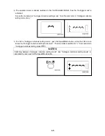
• Toggle the Main switch (2) to ON and OFF alternately to verify
that power is correctly turned ON or OFF.
• Turn ON the Transmitter, then toggle the Main switch (2) to ON, in
addition, and confirm next that the two dots in the Monitor display
as shown in the figure in the light blink.
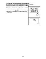
NOTES
In the condition that the Transmitter is not powered ON , or
reception has an error, the Monitor display shows the error code,
“E2”, when the Receiver is turned ON.
Summary of Contents for MC-174CRM
Page 2: ......
Page 8: ...0 6...
Page 60: ...2 38 31 Precautions for use portable card 101 2141000...
Page 62: ...2 40...
Page 77: ...3 15...
Page 117: ...3 55 5 Push the choke knob forward to return the original position...
Page 195: ...4 23...
Page 197: ...4 25...
Page 214: ...5 4 2 OVERALL DIMENSIONS...
Page 215: ...5 5 3 OUTRIGGER SPREAD DIMENSIONS...
Page 219: ...5 9 5 WORKING RANGE...
Page 220: ...5 10...


