


4-13
8.6 IRREGULAR MAINTENANCE
[1] REPLACEMENT RUBBER TRACK
• The inside of the tension adjusting device of the rubber track is greased. Grease is under high
pressure associated with the tension of the rubber track. Failure to follow precautions stated
below when removing grease may lead to a serious accident due to the grease valve popping
out.
• Only one full turn of the tension adjusting grease valve is allowed when loosening. The
grease valve may pop out if disregarded.
• Always stand aside when conducting tension adjustment of the grease valve to circumvent
potential dangers.
• Ensure that grease is completely removed from the inside of the rubber track before rotating
the sprocket to remove the rubber track.
[REMOVAL RUBBER TRACK]
•
Have a steel pipe available.
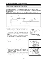
1.
See “Operation 2.13 Outrigger Set Up Operation” to set up the
outriggers and raise the rubber track for about 50mm from the
ground.
2. Remove the 2 mounting bolts (2) and remove the inspection
cover (1).
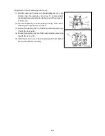
3. Loosen the grease valve (4) gradually and remove grease.
NOTES
Provide only one full turn of the grease valve (1).
4. Insert the steel pipe between the idler and rubber track, as
shown at right. Rotate the sprocket forward.
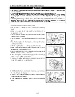
5. When the inserted steel pipe detaches the rubber track from the
idler, slide the crawler in a lateral direction to remove it.
Summary of Contents for MC-174CRM
Page 2: ......
Page 8: ...0 6...
Page 60: ...2 38 31 Precautions for use portable card 101 2141000...
Page 62: ...2 40...
Page 77: ...3 15...
Page 117: ...3 55 5 Push the choke knob forward to return the original position...
Page 195: ...4 23...
Page 197: ...4 25...
Page 214: ...5 4 2 OVERALL DIMENSIONS...
Page 215: ...5 5 3 OUTRIGGER SPREAD DIMENSIONS...
Page 219: ...5 9 5 WORKING RANGE...
Page 220: ...5 10...