background image

215981

134

Revision A

1018931

A

B

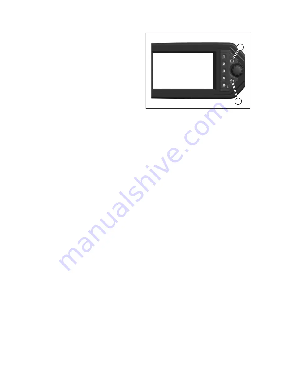
Figure 6.3: HPT

6.

Press BACK button (A) on the HPT to return to the previous
level of the menu structure.

7.

Press HOME button (B) on the HPT to return to the last
selected run screen (or to the header-disengaged screen).

REFERENCE

Summary of Contents for M1170

Page 1: ...M1170 Windrower Unloading and Assembly Instructions North America 215981 Revision A Original Instruction The Harvesting Specialists...

Page 2: ...rmation in this publication is based on the information available and in effect at the time of printing MacDon Industries Ltd makes no representation or warranty of any kind whether expressed or impli...

Page 3: ...forward when they are facing the drive wheels and engine forward when facing the engine This manual uses the terms right cab forward left cab forward right engine forward and left engine forward to r...

Page 4: ...2 1 Checking Operating Safety System page 60 Moved this topic to the Performing Operational Checks section because it must happen after the engine is started Technical Publications Attaching Forming...

Page 5: ...stalling Drive Wheels 20 3 4 Repositioning Right Leg 22 3 5 Repositioning Caster Wheels 25 3 6 Installing Caster Anti Shimmy Dampeners 28 3 7 Installing Windshield Access Step 30 3 8 Positioning Mirro...

Page 6: ...ive Catalytic Regeneration Conditioning Mode 69 4 2 9 Checking Exterior Lights 70 4 2 10 Checking Horn 74 4 2 11 Checking Interior Lights 75 4 2 12 Checking Climate Controls 75 4 2 13 Checking Radio a...

Page 7: ...ance Tracker 133 6 2 Lubricants Fluids and System Capacities 135 6 3 Fuel Specifications 136 6 4 Coolant Specifications 137 6 5 Torque Specifications 138 6 5 1 Metric Bolt Specifications 138 6 5 2 Met...

Page 8: ......

Page 9: ...y Alert Symbols The safety alert symbol indicates important safety messages in this manual and on safety signs on the machine 1000915 Figure 1 1 Safety Symbol This symbol means ATTENTION BECOME ALERT...

Page 10: ...l result in death or serious injury WARNING Indicates a potentially hazardous situation that if it is not prevented could result in death or serious injury It may also be used to alert you to unsafe p...

Page 11: ...oves Wet weather gear Respirator or filter mask 1000005 Figure 1 3 Safety Equipment In addition take the following precautions Be aware that exposure to loud noises can cause hearing impairment Wear s...

Page 12: ...the functionality and or safety of the machine It may also shorten the machine s service life To avoid injury or death from the unexpected startup of the machine ALWAYS stop the engine and remove the...

Page 13: ...ulic system operates under extremely high pressure Makeshift repairs can fail suddenly and create hazardous conditions 1001207 Figure 1 9 Hydraulic Pressure Hazard Wear proper hand and eye protection...

Page 14: ...essary Ensure that the tire is correctly seated on the rim before inflating it If the tire is not correctly positioned on the rim or is overinflated the tire bead can loosen on one side causing air to...

Page 15: ...flush it with cool clean water for 5 minutes Call a doctor immediately If electrolyte is spilled or splashed on one s clothing or their body neutralize it immediately with a solution of baking soda an...

Page 16: ...ormed on the machine IMPORTANT Ensure that the windrower is parked on a level surface the ignition is turned off and the key is removed before disconnecting anything The following items need to be dis...

Page 17: ...ors insert the end of a small 3 6 mm 1 8 1 4 in blade screwdriver into the connector s locking tab Gently pry upward no more than 6 mm 1 4 in to unlock the connector tab and then pull the connector aw...

Page 18: ...rs A Two round connectors C1 and C2 Location Under the cab 1017627 A Figure 1 22 Roof Connectors Roof connectors A Four connectors C10 C12 C13 and C14 Location Under the cab at the base of the left ca...

Page 19: ...ors C25 and C26 Location Under the center of the frame just behind the front cross member IMPORTANT To connect the circular Deutsch connectors without bending the pins fully align the plug with the re...

Page 20: ...cedure in the Starting Engine section of the operator s manual Following the correct procedure will help prevent major damage to engine components and prevent personal injury To ensure that the jacket...

Page 21: ...OT touch the harness connector for the electronic unit injectors while the engine is operating Failure to follow this instruction could result in personal injury or death This engine has a comprehensi...

Page 22: ...ke extra precautions before operating the controls They are usually yellow 1000694 Figure 1 27 Operator s Manual Decal Keep safety signs clean and legible at all times Replace safety signs that are mi...

Page 23: ...er do the following 1 Move the trailer onto level ground Block the trailer wheels 2 Set the forklift s forks to the widest possible setting 1016187 A B C C Figure 2 1 Windrower on Trailer 3 Position t...

Page 24: ...damage Check the rest of the shipment for missing parts 10 In case of shipping damage or missing parts confirm that the serial number matches the one written on the shipping manifest If it does contac...

Page 25: ...osition 1 Locate the left cab forward steps Remove stop bolt A and discard it 2 Loosen pivot bolts B securing steps C 1014555 A B C 1014555 A B C 1014555 A B C Figure 3 2 Left Step Working Position 3...

Page 26: ...dware from toolbox A 1018731 A Figure 3 5 Walking Beam Secured to Frame 3 Remove banding and blocking A securing the walking beam to the frame 4 Retrieve the caster wheel assemblies 1022864 A Figure 3...

Page 27: ...ster assembly B to a suitable lifting device 11 Tilt walking beam C and maneuver caster assembly B so that spindle D can be installed onto walking beam C 1022863 A B C D E Figure 3 9 Caster Arm 12 Ins...

Page 28: ...22781 A B C Figure 3 10 Windrower Supports in Place 1 Have a forklift lift the cab end of the windrower approximately 130 cm 51 in B off of the ground or enough so that left cab forward drive wheel as...

Page 29: ...nuts to 510 Nm 375 lbf ft Follow the tightening sequence shown in the illustration IMPORTANT Use only manufacturer specified lug nuts MD 205397 1029734 1 2 3 4 5 6 7 8 9 10 11 12 Figure 3 13 Tighteni...

Page 30: ...the windrower Use stand A or an equivalent to support the front of the windrower so that right drive wheel B remains off of the ground 2 Slowly lower the windrower onto stand A 3 Place pallet jack C...

Page 31: ...of space in front of the fuel tank NOTE Removing the pins will be difficult if the right leg is bearing any of the wheel s weight 7 Remove the second pin 1022871 A Figure 3 18 Right Leg Ready to Move...

Page 32: ...10 Secure the pins with bolts washers and nuts A Torque the nuts to 136 Nm 100 lbf ft 11 Lower the pallet jack Remove the pallet jack from the work area 12 Support the windrower with a forklift Remov...

Page 33: ...hen swathed produce large windrows 1022900 Figure 3 21 Supporting Windrower 1 Lift the windrower using the forklift so that the casters no longer bear any of the windrower s weight 1018697 A A B C Fig...

Page 34: ...eam and apply anti seize compound to the threads of the bolts Install coated bolts and washers A as shown NOTE Depending on the position of the walking beam the outboard bolts may need to be installed...

Page 35: ...5981 27 Revision A 1013124 Figure 3 27 Walking Beam Adjustment 10 Repeat Steps 2 page 25 to 9 page 26 to reposition the left cab forward caster 11 Lower the windrower to the ground ASSEMBLING WINDROWE...

Page 36: ...key and arm D and secure it with retaining ring E on the caster shaft as shown e Tighten nut C and torque it to 195 Nm 144 lbf ft 1020058 A B C D Figure 3 29 Anti Shimmy System Left Cab Forward Side...

Page 37: ...and torque it to 138 Nm 102 lbf ft 9 Tighten bolts D at the barrel end of the anti shimmy dampeners and torque them to 138 Nm 102 lbf ft IMPORTANT Ensure that the arm is parallel to the walking beam w...

Page 38: ...tep and the railing 2 Retrieve three self tapping screws from the bag in the toolbox NOTE If necessary use the ignition key to unlock the toolbox compartment 1016246 A C B Figure 3 33 Windshield Acces...

Page 39: ...ght in the swivel mechanism 1014674 A B Figure 3 35 Mirror Arm in Working Position 4 Tighten retaining nut A to 39 Nm 29 lbf ft 5 Tighten pivot nut B to 26 Nm 19 lbf ft 1019966 A B C D E Figure 3 36 R...

Page 40: ...rtment 1014590 A B C Figure 3 37 SMV Sign Installed on Mirror Light Support Right Cab Forward Side 2 Position sign A on already installed bracket B on the right cab forward side mirror light support a...

Page 41: ...r use in the United States of America 1019824 A Figure 3 39 SIS Decal USA Only 1 Locate the already installed speed identification symbol SIS decal bracket on the left mirror lighting arm 2 Wipe the a...

Page 42: ...port 1 1 B6047 D135XL 10 6 m 35 ft single reel double knife untimed Transport upper cross auger vertical knives 1 2 B6047 D135XL 10 6 m 35 ft double reel double knife untimed Base 1 1 0 D135XL 10 6 m...

Page 43: ...and lift the hood to open it 1022925 A A A A B D C Figure 3 41 Rear Light Bezel Attached to Windrower 4 Remove eight hex flange bolts A 5 Gently pull light bezel assembly B so that plugs P215 C and P...

Page 44: ...ar of the weight bracket 9 Install weights A from the outboard side of the windrower Slide the weights to the middle of the bracket on the walking beam 10 Install retaining bracket B on each side of t...

Page 45: ...nect plug P215 to the back of red tail brake light E 14 Loosely secure left bezel A to the frame with four hex flange bolts B 15 Repeat Step 12 page 37 and Step 13 page 37 16 Attach plug P210 to right...

Page 46: ...3204 A Figure 3 49 Engine Compartment 19 Grasp the hood by louver A and lower it until the hood engages the latch NOTE To ensure the hood has latched securely make sure that the latch lever is not til...

Page 47: ...ng to avoid injecting dirt and grit into the fitting 2 Inject grease through the fitting with a grease gun until the grease overflows the fitting Do NOT overgrease the wheel bearings 3 Leave excess gr...

Page 48: ...stic caps from the battery posts if these are present 1012747 B A Figure 3 53 Battery Cables Installed 5 Attach the red positive cable terminals to positive posts B on the batteries Tighten the termin...

Page 49: ...ps 1018916 A B C Figure 3 54 Battery Cover Secured 7 Swing cover A towards the windrower frame Lift up on the cab end of the cover until it is secured by retaining tab B on the frame 8 Grasp the hood...

Page 50: ......

Page 51: ...hecks and adjustments listed on the Predelivery Checklist page 149 the yellow sheet attached to this instruction to ensure that the machine is field ready Ensure that the Operator or the Dealer retain...

Page 52: ...ompartment require service DANGER To prevent bodily injury or death from the unexpected startup of the machine always stop the engine and remove the key from the ignition before leaving the operator s...

Page 53: ...y secured for the engine to work correctly 1015818 A A B Figure 4 6 Engine Air Intake 1 Ensure that engine air intake ducting A is securely fastened Tighten the hose clamps as needed 2 Ensure that end...

Page 54: ...between the LOW L and HIGH H marks on the dipstick If the oil level is below the LOW mark oil will need to be added to the crankcase NOTE Adding 1 9 liters 2 U S quarts of engine oil will raise the l...

Page 55: ...lass IMPORTANT If oil is not visible in the sight glass then the oil level is below the ADD mark on the dipstick This problem should be addressed immediately 3 If the hydraulic oil level is too low ad...

Page 56: ...d 4 Turn drain valve A by hand 1 1 2 to 2 turns clockwise until it is tight 5 Dispose of the fuel in a safe manner 4 1 7 Checking And Adding Engine Coolant Coolant is cycled through the engine to help...

Page 57: ...level is at MAX COLD line B c Replace cap A 4 1 8 Checking Engine Gearbox Lubricant Level and Adding Lubricant Ensure that the gearbox lubricant level is correct in order to maximize the service life...

Page 58: ...4 18 Gearbox Lubricant Check Plug 5 Replace oil level check plug A and the breather cap and tighten both 4 1 9 Checking Air Conditioning Compressor Belts The windrower s air conditioner compressor is...

Page 59: ...res B to 110 kPa 16 psi Drive wheel tires Drive wheel A tire pressures are determined by tire type header size and by the options installed on the windrower Refer to the following table to determine t...

Page 60: ...single reel 10 7 m 35 ft double knife untimed Transport 2 Turf 241 35 D135XL single reel 10 7 m 35 ft double knife untimed Transport upper cross auger vertical knives 3 Bar 241 35 D135XL single reel...

Page 61: ...7 m 45 ft double knife untimed Transport 3 Bar 262 38 D145XL double reel 13 7 m 45 ft double knife untimed Transport 3 Turf 241 35 D145XL double reel 13 7 m 45 ft double knife untimed Transport upper...

Page 62: ...he normal starting circuitry is bypassed the machine can start while the drive is engaged and potentially start moving Do NOT start the engine from any other position except the operator s seat Do NOT...

Page 63: ...erator Controls 3 Move GSL A into PARK C 4 Turn the steering wheel until it locks IMPORTANT Do NOT attempt to force the wheel out of the locked position or damage to the steering system may occur NOTE...

Page 64: ...ulic oil temperature can be viewed on Run Screen 4 on the Harvest Performance Tracker HPT display IMPORTANT Do NOT operate the starter for longer than 15 seconds at a time If the engine does not start...

Page 65: ...e Towing the windrower can cause damage to the hydrostatic drives Use the following table to diagnose problems with starting the windrower s engine Table 4 2 Engine Start Troubleshooting Problem Solut...

Page 66: ...in the locked centered position Wait for the Harvest Performance Tracker HPT to beep and display a red P symbol to confirm that the parking brake is engaged The following procedure applies to windrowe...

Page 67: ...733 A B Figure 4 29 Wheel Drive 12 Bolt 1 Park the windrower on level ground 2 Rotate the wheel drive until fill drain plug A is at the 12 o clock position and check plug B is at the 3 o clock positio...

Page 68: ...the area 1 With the engine running and the seat base in engine forward mode press the HEADER ENGAGE switch Confirm that the header drive does NOT engage and that the Harvest Performance Tracker HPT di...

Page 69: ...gine to confirm that the HPT displays MOVE GSL INTO PARK The engine should NOT turn over If the engine turns over the safety system requires adjustment Refer to the windrower s technical manual for th...

Page 70: ...16226 Figure 4 32 HPT Display Header Disengaged 2 Start the engine For instructions refer to 4 1 12 Starting Engine page 54 3 If a header is attached to the windrower confirm that the HPT initially di...

Page 71: ...er s performance gauges The functionality of this feature will need to be verified DANGER To prevent bodily injury or death from the unexpected startup of the machine stop the engine and remove the ke...

Page 72: ...the HPT display 4 2 4 Setting Language and Units of Measurement The language and unit of measurement options can be set in the Harvest Performance Tracker s HPT SETTINGS menu 1018926 A B Figure 4 37...

Page 73: ...for a comprehensive list of U S and metric units 4 2 5 Setting Time and Date The time and date can be set in the Harvest Performance Tracker s HPT SETTINGS menu 1018928 A B Figure 4 38 Time and Date...

Page 74: ...racks the windrower s ground speed the area cut and other productivity data 1018927 A B Figure 4 40 Tire Size 1 Press soft key 5 and use the HPT scroll knob to navigate to the SETTINGS menu For instru...

Page 75: ...installed once the correct tire size is selected press the BACK button to deselect the list of tire sizes Scroll to SELECT POWER WHEEL OPTION A NOTE Do NOT select this option unless the high torque 3...

Page 76: ...on 3 Check engine speed A on the Harvest Performance Tracker HPT display Compare the current engine speed to the value in the table below 4 Move the throttle to its highest possible setting 5 Check en...

Page 77: ...ioning mode is on then indicator A will be highlighted This will prevent the SCR process from occurring NOTE If the SCR system is inhibited for an extended period the engine will begin to derate its p...

Page 78: ...m consists of the following field lights swath lights road lights hazard lights high low beams turn signals and the rotary beacon Any plastic film over these lights will need to be removed All parts o...

Page 79: ...odels with LED lighting remove the plastic film from the LED lighting 2 Rotate the operator s seat to the cab forward position 3 Press FIELD LIGHT switch A 4 Ensure that front field lights B rear fiel...

Page 80: ...nd rear red tail brake lights C are functional 6 Press HIGH LOW switch D Ensure that lights B are functional 7 Press TURN SIGNAL switches E on the console Ensure that amber lights F are functional 8 P...

Page 81: ...e that front road lights B and rear red tail brake lights C are functional 12 Press HIGH LOW switch D Ensure that lights B are functional 13 Press TURN SIGNAL switches E on the console Ensure that amb...

Page 82: ...ctional 17 Press BEACON switch A to shut off the beacons 4 2 10 Checking Horn The horn is a safety device for notifying other people of the windrower s presence The functionality of the horn will need...

Page 83: ...m that the light turns on 5 Push the LIGHT switch to DOOR position C Confirm that the light is off 6 Open the door and check that the light turns on Leave the door open 7 Push switch A to OFF position...

Page 84: ...ch in the ON position for 1 second e Move A C switch C to the OFF position for 5 to 10 seconds f Repeat the A C refresh procedure 10 more times 1015084 A B C D E F Figure 4 57 Climate Controls 3 Press...

Page 85: ...treaming and hands free calling 1036513 A C B D Figure 4 59 Radio 1 To verify the functionality of the radio follow these steps a Turn the ignition key to the RUN position b Press POWER button A to tu...

Page 86: ...u will appear on screen C c Rotate VOL SEL B to highlight the BT SET menu and press the VOL SEL knob to select it BLUETOOTH ON OFF will appear on screen C d Press the VOL SEL knob to select BLUETOOTH...

Page 87: ...the manuals in the windrower s manual storage case will need to be verified 1015166 A Figure 4 61 Manual Storage Case Manuals are stored in manual storage cases A behind the operator s seat 1015175 F...

Page 88: ...STALLED PLACE BAG IN TOOLBOX 1036502 A Figure 4 63 Label for Optional GPS Mounting Kit 2 Inside the cab locate the GPS mount parts bag which has label A 3 If the optional GPS kit will be installed Ins...

Page 89: ...ete its hydraulic and electrical connections Attaching A40DX Auger Header The windrower s support feet and center link will need to be connected to the auger header The windrower may be equipped with...

Page 90: ...83 If the HPT does NOT display a message saying that the float should be removed then proceed to Step 4 page 82 to remove the float manually IMPORTANT To lower the header lift legs without a header o...

Page 91: ...oaches the header 1019351 A B Figure 5 6 Hydraulic Center Link without Self Alignment Kit 9 If the hydraulic center link self alignment kit is NOT installed relocate pin A in the frame linkage as need...

Page 92: ...he header with the REEL DOWN switch on the GSL until it locks into position and hook release D is in the down position 14 If the hydraulic center link self alignment kit is installed check that the ce...

Page 93: ...safety prop fits over the rod 1000711 A Figure 5 11 Header Support 19 Install clevis pin A through the support and the foot and secure it with a hairpin Repeat this step for the opposite support IMPO...

Page 94: ...NOTE If the safety prop will NOT disengage raise the header to release the prop 1014802 A Figure 5 14 GSL DANGER Ensure that all bystanders have cleared the area 24 Start the engine and press HEADER...

Page 95: ...the key from the ignition 30 Grasp one end of the auger header and lift it The lifting force used should be 357 N 80 lbf Repeat this step on the other side of the header Connecting A40DX Auger Header...

Page 96: ...es to prevent contamination of the hydraulic system 7 Push button A on the rear multicoupler receptacle and rotate handle B away from the windrower 8 Open cover C Position multicoupler D onto the rece...

Page 97: ...being replaced by an auger header Remove hose A from storage location B Connect hose A to knife pressure receptacle C on the frame NOTE Hose quick disconnect C is only present on M1170 Windrowers with...

Page 98: ...conditioner then the forming shield should be installed on the windrower The forming shield is not required if the windrower will be paired with an A40DX GSS Auger Header though it can be useful for c...

Page 99: ...pin from clevis pin A at the forward end of the forming shield Remove and retain the clevis pin 4 Repeat the previous step on the other side of the forming shield 1016376 A Figure 5 27 Forming Shield...

Page 100: ...a D1X or D1XL Series Draper Header to a windrower and to complete its hydraulic and electrical connections Attaching Draper Header Supports Draper header supports are required to attach the header to...

Page 101: ...d center link will need to be connected to the draper header The windrower may be equipped with an optional self aligning hydraulic center link which allows control over the vertical position of the c...

Page 102: ...re B b Remove support bracket A Place the bracket and the hardware in the toolbox c Repeat on the opposite side 1016889 A B Figure 5 33 Center Link without Self Alignment 3 Windrowers without the self...

Page 103: ...UT a header or weight box attached to the windrower fully release the tension in header float springs A If the Harvest Performance Tracker HPT displays a message saying that the float should be remove...

Page 104: ...D E F Figure 5 38 GSL Switches A Reel Down B Reel Up C Header Tilt Down D Header Tilt Up E Header Down F Header Up 10 Windrowers equipped with the self aligning center link kit a Press HEADER DOWN swi...

Page 105: ...h the self aligning center link kit a Adjust the position of center link cylinder A with the switches on the GSL until hook B is above the header attachment pin IMPORTANT Hook release C must be down t...

Page 106: ...cking mechanism to function If the hook release is open in the up position manually push it down after the hook engages the pin d Check that center link A is locked onto the header by pulling upward o...

Page 107: ...the safety prop fits over the rod 1000771 A B C D Figure 5 44 Header Leg 18 Install pin B through the header leg Ensure that the pin engages the U bracket in the draper header support Secure the pin...

Page 108: ...r right float C Press knob A to activate the selection 24 Rotate scroll knob A to adjust the float setting Press the knob to confirm the setting IMPORTANT Adjusting the float by increments of 1 0 out...

Page 109: ...c hose management system B rearward to disengage the arm from the latch 2 Move hydraulic hose management system B toward the left cab forward side of the windrower 1015479 A B Figure 5 50 Left Cab For...

Page 110: ...frame NOTE Hose quick disconnect F is only present on M1170 Windrowers with the R1 Series Hydraulic Drive kit MD B6845 installed 10 Remove the cover from electrical connector E Push the electrical con...

Page 111: ...ight as possible IMPORTANT Straight routing will prevent abrasion damage to the hydraulic hoses 1015478 A B Figure 5 55 Left Cab Forward Platform 15 Push latch A to unlock platform B 1012700 A Figure...

Page 112: ...8 Rubber Strap Securing Forming Shield onto Windrower Leg 2 Attach rubber strap D to straight pin C at the rear of the windrower leg Secure it with washer B and lynch pin A 3 Repeat Step 1 page 104 to...

Page 113: ...link B until the hook is above the attachment pin on the header Replace pin A to hold the center link in place IMPORTANT Ensure that the center link is positioned high enough that it does not contact...

Page 114: ...o Step 6 page 106 to remove the float manually IMPORTANT To lower the header lift legs without a header or weight box attached to the windrower ensure that the tension on the float springs is fully re...

Page 115: ...ward until the feet engage the supports and the header is nudged forward 12 Ensure that feet A are properly engaged in supports B 1016903 A B C Figure 5 66 Hydraulic Center Link 13 Windrowers equipped...

Page 116: ...cking mechanism to function If the hook release is open in the up position manually push it down after the hook engages the pin d Check that center link A is locked onto the header by pulling upward o...

Page 117: ...3024 A B Figure 5 70 Header Support 18 Install clevis pin A through the support and windrower lift arm and secure it with hairpin B Repeat this step for the opposite side of the header IMPORTANT Ensur...

Page 118: ...n B and press the scroll knob to select it The float setting page appears 1019607 A Figure 5 74 HPT Display 23 Press soft key 3 A to restore the header float NOTE If the header float is active the ico...

Page 119: ...orward Platform 3 Pull platform A toward the cab until it stops and the latch is engaged 1019603 A Figure 5 77 Hose Support Attachment 4 Attach hose support A to the frame near the windrower left cab...

Page 120: ...o the receptacles on the windrower as follows a Connect the pressure hose female coupler to receptacle A b Connect the return hose male coupler to receptacle B c Connect the case drain hose coupler to...

Page 121: ...ive Calibrate the knife drive whenever you are Attaching the header to the windrower for the first time Changing the speed sensor or hydraulic drive motor on the header Changing the header drive pump...

Page 122: ...3 Rubber Strap Securing Forming Shield onto Windrower Leg 2 Attach rubber strap D to straight pin C at the rear of the windrower leg Secure it with washer B and lynch pin A 3 Repeat Step 1 page 114 to...

Page 123: ...e ignition 1016889 A B Figure 5 85 Hydraulic Center Link 2 Windrowers equipped with a hydraulic center link without self alignment Remove pin A and raise center link B until the hook is above the atta...

Page 124: ...ight box attached to the windrower fully release the tension in header float springs A If the Harvest Performance Tracker HPT displays a message saying that the float should be removed then remove the...

Page 125: ...tract the header lift cylinders 12 Windrowers equipped with a self aligning hydraulic center link Press REEL UP switch B on the GSL to raise the center link until the hook is above the attachment pin...

Page 126: ...ocked onto the header by pressing the REEL UP switch on the GSL 1016901 A B Figure 5 94 Hydraulic Center Link 16 Windrowers without the self aligning center link kit a Press the HEADER TILT UP or HEAD...

Page 127: ...as follows a Pull lever A toward you to release it and then rotate it toward the header to lower the safety prop onto the cylinder b Repeat the previous step for the opposite lift cylinder IMPORTANT E...

Page 128: ...se the header to release the prop 1014802 A Figure 5 99 GSL 22 Start the engine and press HEADER DOWN switch A on the GSL to fully lower the header 23 Shut down the engine and remove the key from the...

Page 129: ...ll hydraulic couplers 1015479 A B Figure 5 102 Left Cab Forward Platform 1 Approach platform A on the left cab forward side of the windrower Ensure that the cab door is closed 2 Push latch B and pull...

Page 130: ...ct the hydraulic hoses to the windrower as follows a Connect disc pressure hose A fitted with red cable tie B to hard plumb fitting C fitted with a red cable tie and torque the connection to 215 Nm 15...

Page 131: ...uick Couplers 8 Quick couplers Connect the hydraulic hoses to a windrower with quick coupler fittings as follows a Connect disc pressure hose A to coupler B Torque the connection to 216 Nm 159 lbf ft...

Page 132: ...n the windrower frame c Remove the cap not shown from inboard bulkhead fitting E Connect hose F red cable tie to inboard bulkhead fitting E NOTE The other end of hose F connects to the grass seed modu...

Page 133: ...e control kit Connect electric baffle control harness C to adapter harness D 13 Grass seed headers GSS Connect actuator harness C to adapter harness D 1015478 A B Figure 5 111 Left Cab Forward Platfor...

Page 134: ...ng the knife drive refer to Calibrating Knife Drive on Harvest Performance Tracker Display page 127 5 1 5 Adjusting Header Settings on Harvest Performance Tracker The settings for the attached header...

Page 135: ...rmance Tracker Display When a header is attached to the windrower the windrower s Harvest Performance Tracker HPT will recognize the header ID and choose the appropriate settings for that header Befor...

Page 136: ...tcut button on the operator s console will also open the WINDROWER SETTINGS menu 1036869 A Figure 5 117 Calibration Selection Screen 7 In the Calibration Selection screen scroll to KNIFE DRIVE A and p...

Page 137: ...ion is complete press PLAY icon A on the screen to continue with Stage 2 of the calibration process NOTE Knife drive calibration consists of nine stages 1014673 A Figure 5 121 Calibration Page 11 Pres...

Page 138: ...he sensor wiring and connectors for an intermittent connection Replace the sensor Calibrating Header Position Sensors on Harvest Performance Tracker Display The header position sensors need to be reca...

Page 139: ...ON screen scroll to POSITION SENSORS A and press SELECT 1014673 A Figure 5 126 Calibration Screen NOTE Pressing X icon A on the screen or pressing the HOME BACK or any GSL button buttons not shown at...

Page 140: ...ADER FLOAT setting or press HOME or BACK button not shown to exit NOTE The engine speed returns to the speed prior to calibration when stage two calibration is complete 1018938 Figure 5 129 Sample of...

Page 141: ...930 A Figure 6 1 HPT Scroll Knob 1 Turn rotary scroll knob A clockwise to move the selection cursor down the screen to the right of the screen clockwise or to increase a selected setting Push the scro...

Page 142: ...1 A B Figure 6 3 HPT 6 Press BACK button A on the HPT to return to the previous level of the menu structure 7 Press HOME button B on the HPT to return to the last selected run screen or to the header...

Page 143: ...1 cSt 40 C Viscosity at 9 5 cSt 100 C 60 liters 15 8 U S gallons 3 Gearbox lubricant Gearbox SAE 75W 140 or 80W 140 API service class GL 5 fully synthetic gear lubricant SAE J2360 preferred 2 1 liters...

Page 144: ...0 05 maximum 40 104 minimum 520 Microns ULSD Grade No 1 and 2 mix4 n a 1 maximum 0 5 maximum preferred 0 1 maximum 45 55 113 130 cold weather high altitude 460 Microns In extreme situations when avai...

Page 145: ...al properties Provides cylinder cavitation protection according to a fleet study run at or above 60 load capacity Protects the cooling system metals cast iron aluminum alloys and copper alloys such as...

Page 146: ...screws Refer to the standard torque values when installing the self tapping screws Do NOT install the self tapping screws on structural or otherwise critical joints 6 5 1 Metric Bolt Specifications Sp...

Page 147: ...65 72 48 53 14 2 0 104 115 77 85 16 2 0 161 178 119 132 20 2 5 314 347 233 257 24 3 0 543 600 402 444 1001370 1001370 A Figure 6 6 Bolt Grades Table 6 4 Metric Class 10 9 Bolts and Class 10 Free Spin...

Page 148: ...num Specifications are provided for the appropriate final torque values for various sizes of metric bolts in cast aluminum NOTE The torque values provided in the following metric bolt torque tables ap...

Page 149: ...g A is NOT on the threads Adjust O ring A if necessary 4 Apply hydraulic system oil to O ring A 1003432 D A E B C Figure 6 10 Hydraulic Fitting 5 Install fitting B into the port until backup washer D...

Page 150: ...ame type and size of fitting found in this topic use the value specified in the procedure instead 1004663 A B C Figure 6 11 Hydraulic Fitting 1 Inspect O ring A and seat B for dirt or defects 2 Ensure...

Page 151: ...edure instead Torque values are shown in the Table 6 9 page 144 1001376 Figure 6 12 Hydraulic Fitting 1 Ensure that the sealing surfaces and the fitting threads are free of burrs nicks scratches and a...

Page 152: ...ntamination 2 Apply paste type pipe thread sealant to the external pipe threads 3 Thread the fitting into the port until it is hand tight 4 Torque the connector to the appropriate torque angle The tur...

Page 153: ...read Tapered Pipe Thread Size Recommended TFFT Recommended FFFT 1 8 27 2 3 12 18 1 4 18 2 3 12 18 3 8 18 2 3 12 18 1 2 14 2 3 12 18 3 4 14 1 5 2 5 12 18 1 11 1 2 1 5 2 5 9 15 1 1 4 11 1 2 1 5 2 5 9 15...

Page 154: ...er m x 3 2808 foot ft Power kilowatt kW x 1 341 horsepower hp Pressure kilopascal kPa x 0 145 pounds per square inch psi Pressure megapascal MPa x 145 038 pounds per square inch psi Pressure bar Non S...

Page 155: ...omposition tube DWA Double Windrow Attachment ECM Engine control module EEC Eco engine control Engine forward Windrower operation with Operator and engine facing in direction of travel FFFT Flats from...

Page 156: ...and externally threaded fastener that threads into preformed threads or forms its own thread when inserted into a mating part SK Single knife SKD Single knife drive Soft joint A flexible joint made b...

Page 157: ...4 1 4 Checking and Adding Engine Oil page 46 Check the level of hydraulic oil Ensure that there are no hydraulic fluid leaks 4 1 5 Checking and Adding Hydraulic Oil page 47 Check the fuel separator fo...

Page 158: ...nal lights are functioning properly 4 2 9 Checking Exterior Lights page 70 Ensure that the beacons are functioning properly if these are installed 4 2 9 Checking Exterior Lights page 70 Complete the h...

Page 159: ......

Page 160: ...STOMERS M Ma ac cD Do on n c co om m DEALERS P Po or rt ta al l M Ma ac cD Do on n c co om m Trademarks of products are the marks of their respective manufacturers and or distributors Printed in Canad...

Reviews: