background image

32       

MT-700


Press and hold the 

 key.  Menu topics appear in the display. 


Use the 

SELECT/ENT

 knob to position the cursor on the 

LAMP

 topic. 


Push the 

SELECT/ENT

 knob.  The 

BRIGHTNESS

 adjust screen appears in the 

display. 

USA

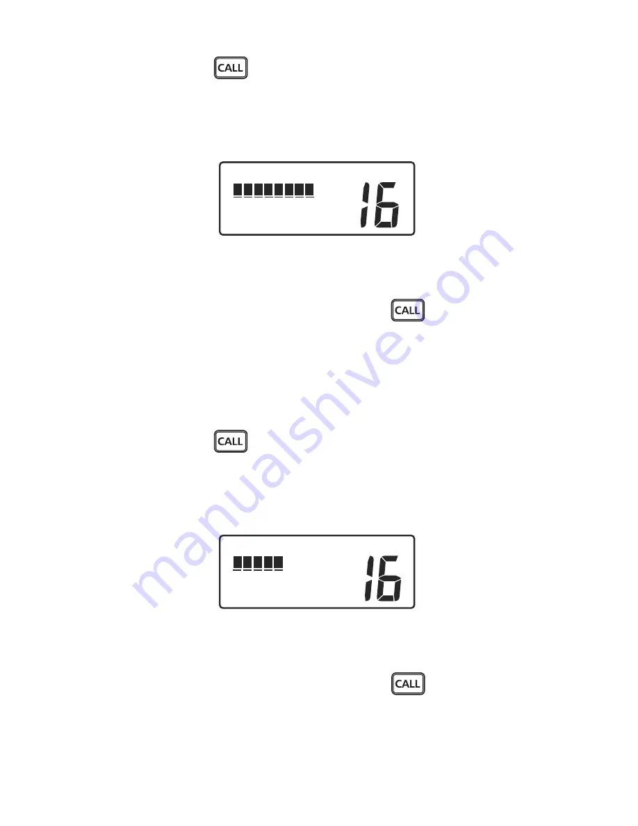
INT

BRIGHTNESS

LO      HI


Brightness Control 


Use the 

SELECT/ENT

 knob or microphone keys 0~3 to change the setting. 


Push the 

SELECT/ENT

 knob or press and hold the 

  key to store the setting 

and exit. 

CONTRAST 

Allows adjustment of LCD display contrast for best readability in varying lighting 
conditions. 


Press and hold the 

 key.  Menu topics appear in the display. 


Use the 

SELECT/ENT

 knob to position the cursor on the 

CONTRAST

 topic. 


Press the 

SELECT/ENT

 knob.  The 

CONTRAST

 adjust screen appears in the 

display. 

USA

INT

CONTRAST

LO      HI


Contrast Control 


Use the 

SELECT/ENT

 knob or microphone keys 0~7 to change the setting. 


Press the 

SELECT/ENT

 knob or press and hold the 

  key to store the setting 

and exit. 

DATA SET 

Provides On/Off control for display of Lat/Lon, Date/Time, Speed/Course, and 

Summary of Contents for MT-700

Page 1: ...OWNER S HANDBOOK MT 700 MENU...

Page 2: ...2001 05 EN 50385 2002 EN 60945 2002 ETSI EN 301 843 1 V1 2 1 2004 06 All essential radio test suites have been carried out NOTIFIED BODY EMCCert Dr Rasek Address Boelwiese 5 91320 Ebermannstadt Germa...

Page 3: ...o generates and radiates radio frequency RF electromagnetic energy EME This equipment must be installed and operated in accordance with the instructions contained in this handbook Failure to do so can...

Page 4: ...Calling Another Vessel 10 3 3 Telephone Calls 10 3 4 Prohibited Communication 11 4 INSTALLATION 12 4 1 Transceiver 12 Dimentions 12 FM 03 Flush Mount Kit Installation 13 4 2 Antenna 13 4 3 Cable Conn...

Page 5: ...itter Power Setting 24 6 5 Channel Scanning 24 Priority Scan 25 All Scan 25 Memory Scan 26 6 6 Menu Functions 27 6 7 Main Menu Topics 28 Directory 28 Lamp 31 Contrast 32 Data Set 32 MMSID Set 36 ATIS...

Page 6: ...ition Send 59 Position Request 60 8 5 Receiving DSC Calls 62 Individual Call Received 63 Last Call Received 64 All Ship s Call Received 65 Group Call Received 67 Position Send Received 67 Position Req...

Page 7: ...nce will not occur in a particular installation If this radio does cause harmful interference to marine electronic equipment which can be determined by turning this radio Off and On the user is encour...

Page 8: ...orities 2 1 Digital Selective Calling DSC Capability You must obtain a nine digit maritime mobile service identity MMSI and program it into the unit before you transmit To obtain an MMSI you will be a...

Page 9: ...peaker 30W nominal at 13 6V 4Ohm For Digital Selective Calling DSC VHF communication radios connection to a GPS receiver that provides latitude and longitude coordinates and UTC time for distress mess...

Page 10: ...te 1 Press the microphone Push To Talk button Speak slowly and clearly into the microphone Mayday Mayday Mayday this is your vessel s name your vessel s name your vessel s name 2 Then repeat once Mayd...

Page 11: ...h to the new channel and listen for traffic If necessary wait for traffic to clear and then call the other vessel As communication proceeds end each transmission with over When communication with the...

Page 12: ...services which is charged in addition to any other charges associated with the call 3 4 Prohibited Communication The following communications are prohibited by regulations and violators are subject t...

Page 13: ...tal display LCD Select a location within easy reach and view of the operator and away from your vessel s compass Locate the microphone to avoid entanglement with steering or engine controls both when...

Page 14: ...6 The same works should be done to the other side too 4 2 Antenna Proper installation of a quality VHF antenna is very important to reliable radio communication A good quality unity gain antenna is re...

Page 15: ...d wire to the positive terminal and the Black wire to the negative terminal Connect the barrel terminals on the power cable to the matching color wires and terminals extending from the rear panel of t...

Page 16: ...nnections Wire Color 1 Brown 2 Red 3 Orange 4 Shield NMEA Rx NMEA Rx NMEA Tx Ground NMEA Tx Connect to NMEA Tx of GPS Connect to Ground NMEA Tx of GPS Connect to NMEA Rx of GPS Connect to Ground NMEA...

Page 17: ...e Mic 10m Extension Cable MT 700 Rear Remote Microphone MT RM01 MT RM01 Extension Speaker or Remote Mic Connector MT RM01 Remote Mic and External Speaker Connections Other end of 10m Extension Cable c...

Page 18: ...keypad on the microphone The 4 line LCD displays the current operating status menus for selecting functions and settings for optional features The microphone has a keypad for changing channels and sel...

Page 19: ...iver Off Press and hold the PWR VOL knob until the LCD turns off Volume and Squelch The Volume and Squelch controls have each knob They are independent controls but work together to control audio outp...

Page 20: ...other approved country channels where specifically allowed by government regulations by using the 8 pin com connector Keypad Transceiver A tone is emitted each time a key is pressed A three beep erro...

Page 21: ...the SCAN key starts Memory Scan Cancels DSC calls and Emergency Distress calls Initiates PA FOG menu screen by pressing Also initiates Intercom operation mode by pressing and hold Keypad Microphone T...

Page 22: ...ntercom It has common usability to your MT 700 transceiver except some operations with same Keypad SELECT ENT dial and four lines LCD display Distress Key Back Top Keys PTT Button Power On Off To turn...

Page 23: ...T 700 transceiver but how to adjust is same as MT 700 See the LAMP topic of 6 7 Main Menu Topics section CONTRAST The CONTRAST adjustment works separately from MT 700 transceiver but how to adjust is...

Page 24: ...ransmitter operation is limited to five minutes and the transmitter will automatically stop To establish normal voice communication Press the key to select the Primary Calling Channel The Primary Call...

Page 25: ...ings 25 watts or 1 watt which are indicated by HI or LO appearing in the upper line of the display The normal power setting is HI for all channels where 25 watts is allowed Use the 1 watt setting for...

Page 26: ...l channels except channel 70 Channel 70 is the Digital Selective Calling DSC channel Voice traffic is not permitted on this channel If noisy or busy channels interfere with scanning the interfering ch...

Page 27: ...in the bank Press the key again to advance to the next page of channels The memory channel bank can hold all usable voice communication channels INT ADD DELETE MEM CHANNEL 16 INT ADD DELETE MEM CHANNE...

Page 28: ...mory channel bank is erased except for Channel 16 which remains To start Memory Scan Press the key The Memory Scan channel bank appears in the display Press the key MSCAN appears in the upper line of...

Page 29: ...e the SELECT ENT knob to move the cursor to the desired setting Push the SELECT ENT knob to store the new setting If you change your mind Before pressing the SELECT ENT knob while in an editing mode p...

Page 30: ...Name and ID Screen Push the SELECT ENT knob or key to move the cursor to the first character of the name line SPECIAL NOTE Characters are entered in the name and ID fields using either the SELECT ENT...

Page 31: ...owed in the name but only one is required Enter enough characters to positively identify the entry After the last character in the name is selected and entered push the SELECT ENT knob or key again Th...

Page 32: ...g square and moves to the first character position Use the SELECT ENT knob to move the underline cursor to the character position needing change Push the SELECT ENT knob or key The blinking cursor app...

Page 33: ...ng and exit CONTRAST Allows adjustment of LCD display contrast for best readability in varying lighting conditions Press and hold the key Menu topics appear in the display Use the SELECT ENT knob to p...

Page 34: ...d exit to the previous menu The MANUAL LL data item has 3 options On Off Set The Set option is used to manually enter your approximate Lat Lon position and time of day for distress messages if your GP...

Page 35: ...Manual LL Entry Push the SELECT ENT knob or key to place the blinking cursor on the first character N or S in the Latitude entry line Use the key to toggle N or S to select a hemisphere North or Sout...

Page 36: ...hours and minutes Use 12 hour AM PM format if a or p appear after the minutes characters The SELECT ENT knob or the microphone keys 0 9 toggle the a p setting If neither a or p appear in the Time line...

Page 37: ...ENT knob to position the cursor on the MMSID SET topic Push the SELECT ENT knob The MMSID TYPE menu appears in the display USA INT MMSID TYPE SHIP ID GROUP ID MMSID Type Select Use the SELECT ENT kno...

Page 38: ...key Menu topics appear in the display Use the SELECT ENT knob to position the cursor on the TIME SET topic Push the SELECT ENT knob The TIME FORMAT menu appears in the display INT TIME FORMAT 12 HR 24...

Page 39: ...r ON or OFF When your selection is complete push the SELECT ENT knob to store the setting and exit the menu GPS ALERT Provides ON Off settings for GPS Alert It is usually set to On If data from your G...

Page 40: ...that channel is memory channel You can edit these channel names as you like To edit the channel names Select the channel which you want to edit the channel name Press and hold the key Menu topics app...

Page 41: ...ompleting the entry Press the key to return to the Main display FOG FREQ Allows selection of tone frequency for Fog Horn operation Tone frequency is available to select within the range from 250Hz to...

Page 42: ...ss Call All Ship s Distress or Urgency Call you can select whether your radio automatically switches to Channel 16 or you determine to manually accept or decline the channel change Press and hold the...

Page 43: ...communication through the PA Speaker To enable the PA Hail operation Press the key The PA FOG menu appears in the display INT PA SELECT FOG PA FOG Menu Topics Push the SELECT ENT knob The PA screen LI...

Page 44: ...sel underway and making way STOP Motor vessel underway but stopped not making way SAIL Sailing vessel underway fishing vessel underway or anchored vessel not under command a vessel restricted in her a...

Page 45: ...will receive on the last selected channel and receive DSC calls Transmitting on the last selected channel will not operate 7 3 Intercom When the optional MT RM01 Remote Mic is installed you can make...

Page 46: ...the SELECT ENT dial after pressing the key The key on MT 700 The key on MT RM01 may be used to exit the Intercom mode and return to the Normal Communication screen NOTE While the Intercom mode is acti...

Page 47: ...RI HI MEM CHANNEL SET GPS DATA NOW Set Manual Lat Lon This warning screen reminds you to manually enter Lat Lon coordinates See the MANUAL LL item of the DATA SET topic of the 6 7 Main Menu Topics If...

Page 48: ...ct the nature of distress USA INT DISTRESS Grounding HOLD 3 SEC Select the Nature of Distress Hold the red button as soon as the button is pressed again an intermittent acoustic alarm is sounded and t...

Page 49: ...is active Unless canceled the distress message is automatically re transmitted every 3 1 2 to 4 1 2 minutes Re transmissions of DSC distress calls are canceled automatically when a DSC acknowledgment...

Page 50: ...sent by a coast station to another vessel in distress In such cases you should maintain a listening watch on channel 16 and standby to lend assistance Your MT 700 does not automatically reply to or r...

Page 51: ...Change is OFF INT 20 33 UTC ID323456789 N 28 33 814 W 82 50 169 Distress Alert page 1 Push the SELECT ENT knob The alert is muted and your transceiver is set to Channel 16 INT 20 33 UTC ID323456789 N...

Page 52: ...istressed vessel s MMSID and ACK appear on the second page Maintain a listening watch on channel 16 and standby to lend assistance Distress Relay from another vessel If your MT 700 transceiver interce...

Page 53: ...C call sent by another vessel or a coast station Outgoing calls are made either by selecting a vessel or station name from your directory or by manually entering the vessel or station MMSID number Pos...

Page 54: ...NDIVIDUAL DIRECTORY MANUAL Individual Menu Push the SELECT ENT knob or press the key The directory list appears in the display Use the SELECT ENT knob to select the desired vessel or station name Note...

Page 55: ...NT INDIVIDUAL vessel name ROUTINE WAITING Waiting For Acknowledge When the called vessel acknowledges your call an alert sounds and ACK RECEIVE appears in the lower line of the display INT 16 PRI HI v...

Page 56: ...the MANUAL topic INT INDIVIDUAL DIRECTORY MANUAL Individual Menu Push the SELECT ENT knob or press the key The SET CHannel SET MMSID screen appears in the display Use the SELECT ENT knob or microphon...

Page 57: ...n the lower line of the display INT SET CH 06 08 72 77 SET MMSID WAITING Waiting For Acknowledge When the called vessel or station acknowledges your call an alert sounds and ACK RECEIVE appears in the...

Page 58: ...Ship s call Press the key The call menu appears in the display Use the SELECT ENT knob to select the ALL SHIP S topic INT INDIVIDUAL GROUP ALL SHIP S RECEIVED DSC All Ship s Call Push the SELECT ENT...

Page 59: ...no response to your call press the key The Normal Communication screen appears in the display Group Call Your can arrange with other vessels to use a group MMSID so that any vessel in a group can cont...

Page 60: ...channel Listen for voice replies from vessels which have received your call There is no DSC ACK reply to confirm that your call was received Use the PTT button to continue voice communication The Norm...

Page 61: ...me ROUTINE PRESS CALL Individual Call Screen Use the SELECT ENT knob to select SEND POS INT INDIVIDUAL vessel name SEND POS PRESS CALL Position Send Screen Press the key to send the call Call is made...

Page 62: ...ectory Push the SELECT ENT knob or press the key The directory list appears in the display Use the SELECT ENT knob to select the desired vessel name Note The MMSID s for each entry do not appear in th...

Page 63: ...xcept for Distress each call type is subdivided into one or more priorities All Ship s type receives the following priorities Distress ACK Distress Relay Urgency and Safety Individual type receives th...

Page 64: ...ller To accept an Individual Call Push the SELECT ENT knob to confirm the requested working channel and mute the alert ACK screen appears INT 09 53P name or ID PRESS CALL 16 TO ACK Routine ACK Screen...

Page 65: ...received the oldest entry is lost Making DSC calls from the call log is the like making calls from the DSC calling directory To instantly reply to the last call received or any log entry Press the key...

Page 66: ...pears in the display INT 12 34P name or ID ALL SHIP S 19 SAFETY All Ship s Safety If the calling vessel or station is listed in your DSC calling directory the vessel or station name as it is listed ap...

Page 67: ...or ID ALL SHIP S 20 URGENT All Ship s Urgent when Auto CH Change is ON Push the SELECT ENT knob to mute the alert if you need Press the PTT button to communicate on Channel 16 To accept an All Ship s...

Page 68: ...n on the working channel selected by the caller There is no DSC ACK for Group Calls To decline a Group Call Press the key The call is interrupted and the Normal Communication screen appears in the dis...

Page 69: ...rectory the caller s MMSID appears in the display Also the Reply screen alternates with the Call Received screen To reply to a Position Request Press the key to send your position Press the key to ret...

Page 70: ...ECT ENT knob to position the cursor on the ATIS SET topic Push the SELECT ENT knob The ATIS SET menu appears in the display INT ATIS SET SEA WATERWAYS ATIS Set Menu Rotate the SELECT ENT knob to selec...

Page 71: ...n the ATIS ID topic Push the SELECT ENT knob The ATIS ID menu appears in the display ATIS ID 9000000000 PUSH ENTER TO CHANGE ATIS ID Set Screen Push the SELECT ENT knob The cursor after 9 is blinking...

Page 72: ...Replace the antenna and or coaxial cable if damaged in any way or severely weathered Avoid continuous direct sunlight on the LCD Avoid overextending the microphone cable Do not use solvents or harsh...

Page 73: ...annel blocked by stuck mic button Select a different channel Look for TX annunciator in display No sound from speaker Faulty external speaker or cable Unplug external speaker cable Antenna Have a tech...

Page 74: ...minutes into OPEN or SHORT Temperature Range 15 Degrees C to 55 Degrees C Construction UV Stable Case with Backlighted silicon rubber keypad Die Cast Rear Heat sink LCD Display 4 Lines with 11 charact...

Page 75: ...6 Safety 108 F3E G3ESimplex 100 X X Individual 120 Urgency 110 F3E G3ESimplex 100 X Individual 120 Safety 108 F3E G3ESimplex 100 X Individual 120 Routine 100 F3E G3ESimplex 100 X X Individual 120 Rout...

Page 76: ...f On GPS Display Data is selected from following Date local time LL Position 3 digit for seconds SOG COG LL Position 3 digit for seconds Time Manual LL Position 2 digit for seconds No Data Data Output...

Page 77: ...ond 3000Hz Audio Low Pass Filter is included Hum Noise Less than 40dB RECEIVER Receive Frequencies 156 300Mhz 162 000Mhz 25Khz spacing Sensitivity 0 5 V or less for 20dB SINAD Squelch Range 0 25 V to...

Page 78: ...On simplex channels your transceiver transmits and receives on the same frequency On duplex channels your transceiver transmits on one frequency and receives on another frequency You may communicate...

Page 79: ...ip and On board communications 1W SHIP SHIP 16 S DISTRESS SEFETY AND CALLING DISTRESS 17 S Inter ship and On board communications 1W SHIP SHIP 18 D 156 900 161 500 Public correspondence PORT OPS 19 D...

Page 80: ...78 D 156 925 161 525 Public correspondence Port operations and ship movement INT L 79 D 156 975 161 575 Public correspondence Port operations and ship movement INT L 80 D 157 025 161 625 Public corre...

Page 81: ...80 MT 700...

Page 82: ...Electric Corporation No 202 6 28 Akasaka 9 chome Minato ku Tokyo 107 0052 Japan Phone 81 0 3 3405 5733 Fax 81 0 3 3405 8677 C 2008 Pony Electric Corp K33091B English Manufactured by www m techmarine...

Reviews: