


M3LPA2
P. 6 / 10
EM-2657 Rev.3
5-2-55, Minamitsumori, Nishinari-ku, Osaka 557-0063 JAPAN
Phone: +81(6)6659-8201 Fax: +81(6)6659-8510 E-mail: [email protected]
I/O RANGING & FINE ADJUSTMENTS
After the DIP SW setting is complete, set up the precise
input and output range using the front control buttons. Be
sure that the front control button function is enabled with
the DIP switch setting.
The front LEDs’ colors and flashing patterns help you to
easily identify the transmitter’s status and confirm the set-
up actions in each step of Calibration Modes. Please read
the following explanations referring to “Calibration Flow
Chart” in Page 6.
■
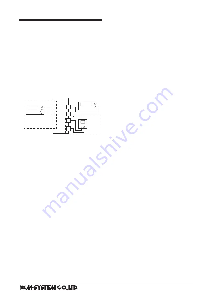
PREPARATION (e.g. M3LPA2-R4/A, DC powered type)
1) Mount the DIP-SW-configured M3LPA2 on to a DIN
rail.
2) Connect the M3LPA2 to a simulator and a multimeter
and to a DC power source as shown below.
3) Turn the power supply on and wait for 10 minutes.
■
INPUT & OUTPUT RANGING
[Example] Setting input to 10 – 80 Hz (DIP SW range 0
– 100 Hz), output to 1 – 5V DC (DIP SW range ±10V).
1) Run Mode: Confirm that the green LED is blinking
(model M3LPA2-x/A) or the green LED turns on (model
M3LPA2-x/B).
2) Threshold Calibration Mode: Press MODE button for
longer than 5 seconds until the LD1 red light is ON.
3) Threshold Setting: Apply the full-scale input level (e.g.
100 Hz) from the simulator and push UP or DOWN but
-
tons until the output meter shows the full-scale output
level (e.g. +10V).
4) Input Calibration Mode: Push MODE button and con
-
firm that the LD1 red light is ON and the LD2 red light
is blinking.
5) 0% Input Ranging: Apply the desired minimum input
level (e.g. 10 Hz) from the simulator and push DOWN
button until the LD1 flashes for approx. 5 sec. and then
turns OFF. When you release the button, the LD1 is re
-
turned to ON.
The flashing LD1 means that the value is stored in the
memory. If LED’s flashing frequency does not change,
the entered level may be inappropriate: too small a span,
or out of usable range (same for all steps).
For setting 0% input to 0 Hz, apply certain frequency be
-
low 1 Hz.
6) 100% Input Ranging: Apply the desired maximum input
level (e.g. 80 Hz) from the simulator and push UP button
until the LD1 flashes for approx. 5 sec. and then turns
OFF. When you release the button, the LD1 is returned
to ON.
7) Output Configuration Mode: Push MODE button and
confirm that the LD1 red light is ON and the LD3 red
light instead of LD2 is blinking.
5
6
7
8
11
12
M3LPA2
Multimeter
Simulator
+
–
Power Source
+ –
+
–
Example with voltage pulse.
See Connection Diagram
for other input types.
Example with
DC power.
8) 0% Output Ranging: Increase or decrease the simulated
input until the meter shows the desired minimum out-
put level (e.g. 1V). Push DOWN button until the LD1
flashes for approx. 5 sec. and then turns OFF. When you
release the button, the LD1 is returned to ON.
9) 100% Output Ranging: Increase or decrease the simu
-
lated input until the meter shows the desired maximum
output level (e.g. 5V). Push UP button until the LD1
flashes for approx. 5 sec. and then turns OFF. When you
release the button, the LD1 is returned to ON.
10
) Run Mode: Programming complete, push MODE button
and confirm that only the LD1 green light is blinking.


