background image

PARTNER II System Programming

Initial System Programming

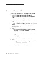
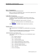
Regardless of whether you are programming the PARTNER System to use
PARTNER MAIL Automated Attendant Service, Call Answer Service or both, you
must program the procedures outlined below. Completing these procedures enables

you to access the PARTNER MAIL hunt group and program the PARTNER MAIL
system.

After you complete the procedures below, refer to “Chapter 4 — PARTNER MAIL
Initial Programming” and perform all initial programming for the PARTNER MAIL
system. After completing the initial programming of the PARTNER MAIL system,
return to this chapter an complete PARTNER System programming for the

PARTNER MAIL Automated Attendant Service and Call Answer Service.

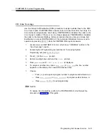
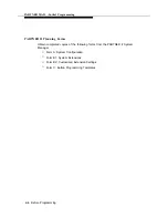
Assign VMS Ports Using
Hunt Group Extensions (#505)

Use this procedure to assign all PARTNER MAIL system extensions (extension jacks

on the PARTNER System’s 206 Module where modular telephone cords from the

PARTNER MAIL system are connected) to VMS Hunt Group 7.

1.

2.

3.

4.

5.

6.

7.

Locate the two or four PARTNER MAIL system extensions on PARTNER II
Form B1.

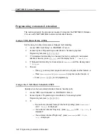
Access System Programming as described in “Accessing System

Programming” and press [ 

#

 ] [ 

5

 ] [ 

0

 ] [ 

5

 ].

Press [ 

7

 ] at the 

Group: 

prompt

NOTE:

To avoid misoperation during a power loss, do not attach the

PARTNER MAIL system to the Power Failure Transfer extensions 10,
16, 22, 28, 34, 40, 46, and 52.

Enter the PARTNER MAIL system EXTENSION at the 

Extension: 

prompt.

Press 

Next Data

 ] 

until the display reads 

1 Assigned

To program the next extension, press 

Next Item

 ] 

or 

Prev Item

 ] 

until the

extension appears, then repeat step 5.

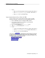
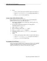
Choose:

Press [ 

#

 ] and the system program number to program another feature,

or

Press 

Next Procedure

 ]  

to program another feature, or

Press 

Feature

 ] 

0

 ] [ 

0

 ] to exit programming.

Initial System Programming   

3-5

Summary of Contents for PARTNER MAIL

Page 1: ...nt Technologies Bell Labs Innovations PARTNER MAIL Voice Messaging System Installation and Use Lucent Technologies formerly the communications systems and technology AT T units of AT T 585 322 101 Iss...

Page 2: ...nces to Lucent Technologies Incorporated The exception is cross references to books published prior to December 31 1996 which retain their original AT T titles Lucent Technologies formed as a result o...

Page 3: ...CAUTION Environmental and electrical conditions must meet the specifications as listed on pages 20 and 21 SAVE THESE INSTRUCTIONS...

Page 4: ...CAUTION DO NOT block or cover the ventilation slots and openings They prevent the product from overheating DO NOT place the product in a separate enclosure unless proper ventilation is provided Addit...

Page 5: ...for Installation 2 2 Installing the PARTNER MAIL Unit 2 4 Add or Replace Voice Processing Card 2 12 3 PARTNER II System Programming PARTNER II System Planning Forms Introduction to System Programming...

Page 6: ...4 4 17 4 25 4 28 4 31 4 33 5 Verifying System Operation 5 1 Automated Attendant Service 5 2 Call Answer Service 5 4 Voice Mailbox Transfer 5 5 Voice Mail Service 5 6 6 PARTNER MAIL Administration Guid...

Page 7: ...Contents Changing Greetings Voice Mail Service 6 51 6 56 7 Troubleshooting 7 1 A Appendix A Factory Settings A 1 Glossary G 1 Index IN 1 iii...

Page 8: ...ER MAIL RMD Switch Settings The PARTNER MAIL Remote Maintenance Device Remove Unit from Wall mount Remove Screw from Unit Voice Processing Card Switch Settings Installing a Voice Card Installing the C...

Page 9: ...6 4 6 5 6 6 6 7 6 8 Administration Menu Hierarchy System Parameters Schedule Changing the Automated Attendant Main Menus Mailbox Administration Options Changing Group Lists Line Ownership System Gree...

Page 10: ...tration instructions this guide contains a table of factory settings in Appendix A a glossary of terms an index and three removable pages located at the back of the guide These pages provide the follo...

Page 11: ...ervice Program Call Answer Service Program Night Service Button Program for the RMD Program Telephone Buttons Initial Programming Program System Parameters Chapter 4 of the PARTNER Program the Schedul...

Page 12: ...Owner Assign System Administrator s Extension Program Fax Message Receiver 2 Schedule Parameters Change the System Date and Time Temporary Schedule Changes 3 Automated Attendant Program Selector Code...

Page 13: ...d of an extension or password you have entered PASSWORD means press the buttons on the dialpad for the appropriate password MAlLBOX means press the buttons on the dialpad to dial the Mailbox number of...

Page 14: ...numbers are listed on the inside front cover Portions of the documentation may be available in French and Spanish For more information contact your AT T authorized representative Guide Title Order Nu...

Page 15: ...e caller with a menu of options so that the call can be routed directly to the desired extension The PARTNER MAIL system routes calls and fax transmissions answers calls provides after hours service a...

Page 16: ...itial settings for the PARTNER System to integrate it with the PARTNER MAIL system The implementor needs the completed planning forms to program the systems System Administrator The PARTNER MAIL Syste...

Page 17: ...onist or system user who is primarily responsible for answering calls Typically this person is also the General Mailbox Owner Fax Message Receiver The Fax Message Receiver is the person to notify when...

Page 18: ...sevices offered by the PARTNER MAIL system Read the following descriptions of the Automated Attendant service Call Answer Service Voice Mail Service and their related features then keep in mind the t...

Page 19: ...ed Call Handling Coverage ON OFF Outcalling Automated Attendant The Receptionist answers all external answers external calls calls immediately The immediately Over Receptionist answers flow calls go t...

Page 20: ...Automated Attendant service is useful for many businesses such as banks insurance agencies post offices and stores A bank could for example use Automated Attendant service to allow its customers to s...

Page 21: ...day only or only during the night The schedule that you select and the greeting that the caller hears depend upon the setting of the PARTNER II Night Service button When Night Service is ON and the H...

Page 22: ...s after the second ring by playing the Automated Attendant Day or Night Greeting Figure 1 2 Callers using rotary phones or callers requesting assistance can be transferred to the receptionist s extens...

Page 23: ...a Fax Message Receiver as described earlier in this chapter Delayed Call Handling An outside call rings at the system extensions If a system user does not answer the call after the fourth ring the PAR...

Page 24: ...wing Create group lists to enable subscribers to send a single message to several subscribers Use the Broadcast feature to send a single message to all subscribers Perform administration of the PARTNE...

Page 25: ...sy or does not answer and the VMS Cover button which enables users to turn VMS Cover ON and OFF at their extension Automatic VMS Cover When VMS cover is activated at the called extension the system gr...

Page 26: ...ing to another extension Voice Mailbox Transfer Users may program buttons on their system phones that allow them to transfer callers directly to another subscriber s voice mailbox without causing the...

Page 27: ...Installation 2 This chapter provides instructions for installing the PARTNER MAIL system and for connecting it to the PARTNER II Communications System Release 3 2 1...

Page 28: ...wing parts PARTNER MAIL Unit PARTNER MAIL Cabinet Wall mount and Cable Manager Bracket and screws NOTE The cabinet and bracket are together referred to as the PARTNER MAIL unit For a single voice proc...

Page 29: ...piece of plywood or attach the PARTNER MAIL unit directly to wall studs This will best ensure permanent mounting and will prevent wall damage To help ensure trouble free operation maintain the followi...

Page 30: ...t on the wall near the PARTNER II Release 3 processor Connecting the unit to the PARTNER II Release 3 system Connecting the Remote Maintenance Device modem to the PARTNER MAIL unit and to the PARTNER...

Page 31: ...he surface so that the slot is upward Figure 2 2 WARNING Be sure to install the wall mounting screws in wall studs or in a piece of plywood to ensure permanent mounting and to prevent wall damage Wall...

Page 32: ...RTNER MAIL unit s bracket lip into the bracket slot 6 Tighten the captive retaining screw into the mounting hole on the unit Wall Slot Rear panel Bracket Lip Captive Remove screw from mounting hole Re...

Page 33: ...L system cords to the top extension jack of any 206 Module or to power failure transfer extensions 10 16 22 28 34 40 46 or 52 NOTE For proper operation do not connect the PARTNER MAIL system cords to...

Page 34: ...ules Primary Processor Module center slot 400 Modules Backplane Extension 16 Extension 12 Extension 11 Extension 13 Extensions 17 18 19 20 Connections Shown are for this example only Figure 2 4 Connec...

Page 35: ...cuit as the PARTNER II Release 3 so that the two units share a common ground 8 Turn the Power Switch ON Figure 2 5 9 After 2 minutes all Status Indicator Lights should be green indicating that all PAR...

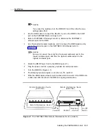
Page 36: ...nce Device to the Unit 1 The RMD switches are preset at the factory Confirm that the switches located on the underside of the RMD are set as shown in Figure 2 6 Figure 2 6 PARTNER MAIL RMD Switch Sett...

Page 37: ...from the lowest numbered port to the lowest numbered jack and from the highest numbered port to the highest numbered jack Attach the RMD Power Cord to the RMD Figure 2 7 Plug the power cord into a pro...

Page 38: ...talled incorrectly Customers with a 2 port configuration may want to upgrade to a 4 port configuration to support a greater volume of calls or an increased number of subscribers To upgrade from two to...

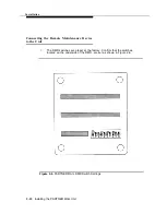
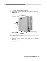
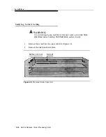
Page 39: ...acket and place it on a sturdy flat tabletop Figure 2 8 Cover screws Lift up and out Loosen retaining Cover screws screw Figure 2 8 Remove Unit from Wall mount 6 Remove the four screws located on the...

Page 40: ...component wear a grounded Static Wrist Band before handling PARTNER MAIL system circuitry 1 Remove the screw from the upper card slot Figure 2 9 2 Remove the clear plastic slot plate Remove screw Sock...

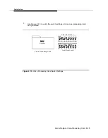
Page 41: ...rify the switch settings on the voice processing card being installed Dip Switch Voice Processing Card Card 1 Ports 1 and 2 Card 2 Ports 3 and 4 Figure 2 10 Voice Processing Card Switch Settings Add o...

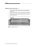
Page 42: ...PARTNER MAIL unit Figure 2 11 2 Install the plastic card spacer so that it holds the upper and lower cards at the center of the unit but does not touch any of the components on either card 3 Tighten...

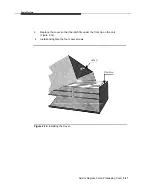
Page 43: ...place the cover so that the latch fits under the front lip on the unit Figure 2 12 5 Install and tighten the four cover screws Latch Front Lip Figure 2 12 Installing the Cover Add or Replace Voice Pro...

Page 44: ...unt and Cable Manager Bracket Wood Mounting Surface Retaining Bracket PARTNER MAIL Bracket Captive Mounting hole for Retaining Captive Retaining Screw Screw Figure 2 13 Mounting the PARTNER MAIL Unit...

Page 45: ...the lowest numbered port to the lowest numbered jack and from the highest numbered port to the highest numbered jack Connect the modular telephone cords from the PARTNER MAIL system ports to the PARTN...

Page 46: ...extension 10 is generally administered as the PARTNER MAIL System Operator s extension you may find it more convenient to program from extension 11 while the receptionist continues to handle calls fro...

Page 47: ...the PARTNER MAIL system Form B1 System Lines Records information for each system extension This includes the type of telephone or auxiliary equipment at the extension the name of the system user or a...

Page 48: ...a few procedures during the programming session and you know the codes For example press 1 0 3 to change the system time Cycle Method enables you to cycle through a sequence of procedures in numerica...

Page 49: ...ata and Prev Data cycle forward and backward through data values offered by a procedure Example 1 Assigned 2 Not Assigned Remove returns the current setting to the factory setting Enter indicates the...

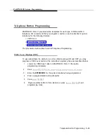
Page 50: ...procedure to assign all PARTNER MAIL system extensions extension jacks on the PARTNER System s 206 Module where modular telephone cords from the PARTNER MAIL system are connected to VMS Hunt Group 7 1...

Page 51: ...nother extension press Next Item or Prev Item until the extension number appears on the display then repeat step 4 Choose Press and a system program number to program another feature or Press Next Pro...

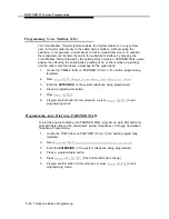
Page 52: ...in Accessing System Programming and press 3 0 4 3 Enter the RMD EXTENSION at the Extension prompt 4 Press Next Data until the display reads 1 Assigned 5 Choose Press and a system program number to pr...

Page 53: ...ed Call Handling is checked press Next Data until the display reads 2 Delayed Choose Press and a system program number to program another feature or Press Next Procedure or Prev Procedure to program a...

Page 54: ...Accessing System Programming and press 2 0 6 Press 7 at the Group prompt Enter a two digit Line number at the Line prompt Press Next Data until 1 Assigned is displayed To program another line press Ne...

Page 55: ...Cover to the extensions listed on Form B2 as described below 1 2 3 4 5 Access System Programming as described in Accessing System Programming and press 3 1 0 Enter the EXTENSION at the Extension prom...

Page 56: ...ystem answers 1 2 3 4 5 6 7 Locate Lines on PARTNER II Form A which have VMS MAIL written in the Line Coverage column Access System Programming as described in Accessing System Programming and press 2...

Page 57: ...rvice Locate the NightSVC label on PARTNER II Form C the button programming template Access System Programming as described in Accessing System Programming and press 5 0 3 Choose To assign Night Servi...

Page 58: ...ver Button F15 To give subscribers the ability to turn Voice Mail coverage ON and OFF you may program a VMS Cover button at the subscriber s system phone as described below 1 2 3 4 5 6 Locate the VMSC...

Page 59: ...Press Feature 0 0 System Program System Program Central Tel Program Enter the EXTENSION of the system telephone being programmed Press a programmable button Press Feature 1 4 Program another button fo...

Page 60: ...MAIL Initial Programming 4 This chapter provides guidelines and procedures for initial programming of the PARTNER MAIL system The terms program and administer are used interchangably throughout this g...

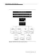
Page 61: ...press on the dialpad Only the System Administrator may program the PARTNER MAIL system by accessing the hidden option 9 from the Voice Mail Menu PARTNER MAIL System Programming Menus Figure 4 1 illust...

Page 62: ...ension Enter System Administrator Password Voice Mail Menu 9 Administration Main Menu System Parameters Automated Attendant Group Lists System Greetings 1 3 5 7 Schedule Mailboxes Line Ownership 2 4 6...

Page 63: ...he hidden menu option 9 from the Voice Mail Menu Press 9 to program The system plays the system programming options Refer to Appendix A for a list of all factory settings You should confirm a factory...

Page 64: ...for instructions Planning Forms Obtain completed copies of all PARTNER II and PARTNER MAIL system planning forms Planning forms provide the names extensions mailboxes and other information required to...

Page 65: ...anning Forms Obtain completed copies of the following forms from the PARTNER II System Manager Form A System Configuration Form B1 System Extensions Form B2 Customized Extension Settings Form C Button...

Page 66: ...ers Figure 4 2 regardless of the services used Administration Main Menu System Parameters 1 Extension Owner Mailbox Receiver 4 5 FAX System General System FAX Extension Operator Mailbox Administrator...

Page 67: ...s described in an earlier section PARTNER MAIL plays the system programming options Press 1 to program System Parameters Press 7 to change the System Administrator Mailbox The current mailbox number p...

Page 68: ...orization from the customer The AT T Helpline phone number is listed on the inside cover of this guide Press Intercom 7 7 7 or a preprogrammed button Enter the System Administrator s MAlLBOX initially...

Page 69: ...r s extension Factory Setting 10 Keep the factory setting unless a new setting is desired Access the Administration Main Menu as described in an earlier section The system plays the system programming...

Page 70: ...ilbox and to change the General Mailbox Owner s password To change the General Mailbox password perform the following Log on using mailbox 9999 Use the same procedure as shown for Changing the System...

Page 71: ...tem to immediately detect fax transmissions and send them to a fax machine Access the Administration Main Menu as described in an earlier section The system plays the system programming options Press...

Page 72: ...Receiver the system does not light the Message Iight at any extension after it receives a fax transmission PARTNER II Release 3 cannot light Message lights on single line telephones Only assign the Fa...

Page 73: ...e Schedule Figure 4 3 illustrates the options available when programming the schedule Administration Main Menu 9 Schedule 2 Update Open or System Date Closed and Time for Today 1 3 Figure 4 3 Programm...

Page 74: ...to program the Schedule Press 1 to program date and time The system plays the current date and prompts you to enter a new date To accept the date played press To enter a new date mmddyy enter the fol...

Page 75: ...he new time NOTE If requested enter 1 for A M or 2 for P M the system prompts you to enter A M or P M when the hour you enter is less than 13 7 Press 1 to reenter or press to accept the time If you pr...

Page 76: ...signed a one digit Selector Code and a corresponding Selector Code Action For example the Main Menu for the ANY Travel Agency offers these options For cruises press 1 For corporate travel press 2 For...

Page 77: ...or Code the system prompts them to enter an extension For example ANY Travel uses extensions 10 through 40 in their dial plan They use Selector Codes 1 through 4 to direct callers to submenus and anno...

Page 78: ...Day or Night Menu or a submenu Tell callers to press to back up to the previous menu or to press 4 to repeat the announcement Create announcements before programming the corresponding Selector Code T...

Page 79: ...ee menu levels tend to confuse callers If you are creating more than one submenu create the lowest level submenu first To eliminate background noise speak into the handset while recording the submenu...

Page 80: ...for each Selector Code When finished go to Step 10 Press to approve The prompt asks you to record the submenu script Record at the tone Lift the handset and record the submenu script Press 1 after rec...

Page 81: ...uncements must be created before the Main Menus Refer to the preceding instructions for Creating Submenus and Creating Announcements To eliminate background noise speak into the handset to record menu...

Page 82: ...Codes Press to approve the Selector Codes The system plays the current Dial 0 Timeout Option followed by the Dial 0 Timeout Option Menu The Dial 0 Timeout Options specify where the system transfers c...

Page 83: ...er the menu prompt plays three times When the Touch Tone gate is ON rotary callers do not have to listen to the Day or Night Menu before being transferred for assistance 1 2 3 4 5 Use Form 4 Automated...

Page 84: ...istance When the Automated Attendant first answers a call it plays a Day or Night greeting then a Day or Night menu Figure 4 5 illustrates the menus for recording system greetings Administration Main...

Page 85: ...eakerphone when recording greetings Access the Administration Main Menu as described in an earlier section The system plays the system programming options Press 7 to program the System Greetings Press...

Page 86: ...g the Touch Tone Gate in a previous section of this chapter Access the Administration Main Menu as described in an earlier section The system plays the system programming options Press 7 to program th...

Page 87: ...a Configuration Mailbox Mailbox Mailbox 2 4 3 6 Figure 4 6 Programming Mailboxes The PARTNER MAIL system is shipped with mailboxes created for extensions 10 through 57 The COS Class of Service descri...

Page 88: ...e mailbox Outcalling Not Permitted if permitted and the subscriber administers outcalling using the Voice Mail Service the system calls a designated telephone or pager whenever a new message is left i...

Page 89: ...ccess the Administration Main Menu as described in an earlier section The system plays the system programming options Press 4 to program Mailboxes Press 6 to modify a Mailbox Enter EXTENSION of mailbo...

Page 90: ...names and extensions of group members Up to 99 Group Lists can be created Make copies of Form 9 and distribute them to all group members 1 Access the Administration Main Menu as described in an earlie...

Page 91: ...PARTNER MAIL Initial Programming 7 When finished entering all extension numbers press to approve the list 8 Press to return to the System Administration menu 4 32 Creating Group Lists...

Page 92: ...p to determine the Line number s that requires coverage and the Line Owner s name and extension If an owner is not assigned to a covered line the system transfers callers who call in on that line to t...

Page 93: ...en finished entering the lines press to return to the Administration Main Menu This concludes the initial programming of the PARTNER MAIL system Refer to Chapter 3 Partner II System Programming to com...

Page 94: ...Verifying System Operation 5 Once you have completed the initial programming of the PARTNER MAIL system and the PARTNER II Release 3 System perform the Acceptance Tests to verify proper operation 5 1...

Page 95: ...on a line assigned to the Automated Attendant Ask the primary call handler not to answer the call 2 Listen for the Automated Attendant Greeting The Automated Attendant service should answer the call a...

Page 96: ...system phone at the Fax Message Receiver extension is ON Night Menu 1 Turn Night Service ON at extension 10 2 Place a call on an incoming line answered by the Automated Attendant 3 Listen for the Nig...

Page 97: ...tension that has VMS coverage CO Line Coverage 1 2 3 4 Call in on a Line assigned to the VMS Line coverage option Do not answer the called Line After 5 ringas the Call Answer Service answers and you s...

Page 98: ...2 Press the programmed button or dial Feature 1 4 3 Dial the requesated extension number or press an Intercom Auto Dial button or Manual Signaling button for that extension 4 Hang up 5 PARTNER MAIL s...

Page 99: ...ying System Operation Voice Mail Service Place an internal call to Intercom 7 7 7 the PARTNER MAIL Hunt Group or press a preprogrammed button You should hear the Voice Mail Greeting 5 6 Voice Mail Ser...

Page 100: ...xplains how to use all menu and submenu options that are accessed from the PARTNER MAIL Voice Messaging System s Administration Main Menu Refer to Chapter 1 Introduction if you require a detailed over...

Page 101: ...ng the next step Entering 7 at any point during system programming will always bring you back to the System Administration Main Menu Entering 9 exits the system You can also hang up Use the handset to...

Page 102: ...ted Attendant service menus and prompts mailbox definitions and so on The menus are arranged in a hierarchy of submenus that you reach using the Administration Main Menu General system subscribers can...

Page 103: ...tension Enter System Administrator Password Voice Mail Menu 9 Administration Main Menu System Automated Group System Parameters Attendant Lists Greetings 1 3 5 7 Schedule Mailboxes Line Ownership 2 4...

Page 104: ...te the planning forms Before programming the system have the applicable PARTNER MAIL system planning forms available Required forms are identified in the instructions when you need them Refer to Chapt...

Page 105: ...nistrator s PASSWORD initially 1 2 3 4 and press The system plays the seven items on the Voice Mail menu Figure 6 1 The PARTNER MAIL system does not play menu item 9 the Administration Menu The System...

Page 106: ...L Automated Attendant service automatically transfers calls to the fax extension if administered Update the fax extension on Form 2 System Parameters and follow the instructions below 1 Access the Adm...

Page 107: ...ameters to determine the System Operator s extension The factory setting for the System Operator s extension is 10 1 2 3 4 5 Access the Administration Main Menu as described in an earlier section The...

Page 108: ...nsion plays and prompts for a new extension Enter the General Mailbox owner s new EXTENSION followed by The new extension number plays followed by the System Parameters Menu Press to return to the Adm...

Page 109: ...4 5 Access the Administration Main Menu as described in an earlier section The system plays the system programming options Press 1 for System Parameters The System Parameters Menu plays Press 8 to pr...

Page 110: ...enever they call The system switches to day or night operation depending on the setting of the Night Service button at the System Operator s extension The System Administrator can temporarily change f...

Page 111: ...te and change the time only by pressing when the date is requested and vice versa 4 Enter the date mmddyy or press to accept the date played mm 01 12 dd 01 31 yy 00 99 Example for May 28 1993 press 0...

Page 112: ...he system to play the factory set Temporary Closure Greeting that states the company is closed for today Program the system to play the Night Greeting which normally plays when your company is closed...

Page 113: ...step 6 Choose Press 0 to listen to the current greeting The system plays the current greeting Press 1 to record a Temporary Closure Greeting The system plays the Message Recording menu Go to step 7 Pr...

Page 114: ...hanging the Main Menus Administration Main Menu Automated Attendant Service 3 Day Night Submenus Announce Touch Tone Menu Menu ments Gate 1 2 3 4 5 Figure 6 4 Changing the Automated Attendant Main Men...

Page 115: ...tions to select Selector Codes and Selector Code Actions work the same on submenus and main menus For example a caller to ANY Travel Agency would hear the following greeting Thank you for calling ANY...

Page 116: ...ted trips Be sure to complete Form 8 Automated Attendant Announcements The announcement must already exist before you can program this action Action 4 Prompted Transfer When callers press a Selector C...

Page 117: ...any changes to a main menu All announcements and submenus that you program as options from a main menu must exist before you program the main menu Playing the Main Menus Use the following procedure t...

Page 118: ...Attendant The Automated Attendant Administration Menu plays 3 Choose Press 1 to select the Day Main Menu The Menu Definition Options play Press 2 to select the Night Main Menu The Menu Definition Opti...

Page 119: ...on 3 Play an Announcement The system prompts you to enter an announcement number Enter announcement number The system confirms the Selector Code and the Selector Code Action Go to step 7 Press 4 to se...

Page 120: ...tone 9 Lift the handset and record the main menu script or press to skip recording NOTE Even if you ve changed only one Selector Code you must re record the entire main menu 10 Press 1 after recording...

Page 121: ...ter a Selector Code from 1 to 9 Press to approve all Selector Codes The current Timeout Action Option plays followed by the Timeout Action Option Menu Choose the Dial 0 Timeout Action that defines whe...

Page 122: ...ed Attendant The Automated Attendant Administration Menu plays Choose Press 1 to select the Day Main Menu The Menu Definition Options play Press 2 to select the Night Main Menu The Menu Definition Opt...

Page 123: ...menu prompt Press 1 after recording The Message Recording Menu plays Choose an option or go to Step 13 Press 2 1 to re record the new main menu prompt Press 2 3 to rewind and listen to the new main m...

Page 124: ...ENSION Go to step 8 NOTE The Submenu and Announcement must exist befor you can select Actions 2 or 3 Press 2 to select Action 2 Play a Submenu The system prompts you to enter a submenu number Enter su...

Page 125: ...nu prompt Press to approve the submenu prompt Press to approve the new submenu prompt The system plays Approved Menu Saved Press to return to the Administration Main Menu Recording the Submenu Prompt...

Page 126: ...or modify a Selector Code refer to Modifying a Submenu earlier in this chapter If you want to delete a Selector Code that is currently assigned to a submenu update form 7 then use the following instr...

Page 127: ...re record the new submenu prompt Press 2 3 to replay the new submenu prompt Press 3 to delete the new submenu prompt and use the one previously recorded Press to approve the new submenu prompt The sy...

Page 128: ...nnouncement 7 Press 1 after recording the announcement The system plays the message Recording Menu 8 Choose an option or go to Step 9 Press 2 1 to re record the announcement Press 2 3 to replay the an...

Page 129: ...the menu three times The Touch Tone Gate is automatically ON if you administer a fax extension and cannot be turned OFF The factory setting is OFF To change the current setting of the Touch Tone Gate...

Page 130: ...Changing Mailbox Assignments Administration Main Menu Mailboxes 4 Play Mailbox Create a Delete a Modify a Configuration Mailbox Mailbox Mailbox 2 4 3 6 Figure 6 5 Mailbox Administration Options Changi...

Page 131: ...y have changed some of the COS settings of the mailboxes In addition subscriber s may have re recorded their name recordings or designated Personal Operators to handle their calls Use the procedure be...

Page 132: ...the system programming options 2 Press 4 for Mailbox programming The Mailbox Administration Menu plays 3 Press 3 to delete the Mailbox NOTE Any messages in the Mailbox are lost when a Mailbox is delet...

Page 133: ...bered extension available e g extension 57 and work backwards toward extension 10 to assign additional Guest Mailboxes The PARTNER MAIL system does not attempt to transfer callers receiving Automated...

Page 134: ...attempts to transfer the call to the extension entered by the caller Not Permitted the system does not attempt to transfer the call to the extension entered by the caller Instead the system transfers...

Page 135: ...o enter the employee s name up to 4 letters followed by The system echoes the letters for confirmation and prompts you to press 9 to confirm the name or to press 6 to cancel the name Letter Key A 21 N...

Page 136: ...1 to write in the changes Change the name on the Mailbox as follows 1 2 3 4 5 Access the Administration Main Menu as described in an earlier section The system plays the system programming options Pre...

Page 137: ...ect the name Choose Press 9 to approve the name The name is saved The prompt says Record the name Go to step 8 Press 6 to disapprove the name The prompt asks you to re enter the name Go to step 6 Lett...

Page 138: ...delete the name Press 2 1 to re record the name Press 2 3 to rewind and listen to the name 10 Press to approve the name 11 Press to return to the Mailbox Administration Menu The Mailbox Administratio...

Page 139: ...ompts you to enter a mailbox number Enter the MAILBOX extension to be modified followed by The system prompts you to press 1 to change the name press 2 to change the Class of Service or Press 3 to ini...

Page 140: ...as follows 1 2 3 4 5 6 Access the Administration Main Menu as described in an earlier section The system plays the system programming options Press 4 for Mailbox programming The Mailbox Administration...

Page 141: ...rator can use the Broadcast feature A Group List consists of any number of extensions assigned to a single group Each Group List is assigned a number When a subscriber enters a Group List number rathe...

Page 142: ...p list form 9 by playing the list number and the number of subscribers in the list 1 2 3 4 5 Access the Administration Main Menu as described in an earlier section The system plays the system programm...

Page 143: ...Menu plays Press 6 to Review and Modify a Group List The system prompts you to enter a Group List number Enter the Group List number followed by The number of entires in the list plays followed by th...

Page 144: ...te a Group List The system prompts you to enter the new Group List number 4 Enter the new Group List number followed by The system prompts you to enter an extension number If you want to use the direc...

Page 145: ...Group Lists The Group List Administration Menu plays Press 3 to delete a Group List The system prompts you to enter the number of the Group List being deleted Enter the number of the Group List to be...

Page 146: ...ure 6 7 Line Ownership The PARTNER MAIL system Line Ownership feature enables you to specify an extension a subscriber who receives messages left by callers who call into the office on a line covered...

Page 147: ...line owner s name or his her extension number Each time you press the system plays the next line number in the list and the name of the line owner or the extension number If no subscriber owns a spec...

Page 148: ...Form 10 to show changes to Line Ownership 1 Access the Administration Main Menu as described in an earlier section The system plays the system programming options 2 Press 6 to program Line Ownership...

Page 149: ...tion Main Menu as described in an earlier section The system plays the system programming options Press 6 to program Line Ownership The Line Ownership Administration Menu plays Press 3 to deallocate a...

Page 150: ...eeting Subscribers wanting to send or receive messages enter the Voice Mail service which then plays the Voice Mail Greeting The factory set Voice Mail Greeting is strongly recommended Welcome to PART...

Page 151: ...orded voice Access the Administration Main Menu as described in an earlier section The system plays the system programming options Press 7 for System Greeting The System Greeting Menu plays Press 1 fo...

Page 152: ...ning to an Automated Attendant Greeting To listen to the greeting that plays when the phone is answered by the Automated Attendant Service follow the instructions below 1 2 3 4 5 6 Access the Administ...

Page 153: ...ange the script on Form 6 Night Greeting and Menu and follow the instructions below 1 Access the Administration Main Menu as described in an earlier section The system plays the system programming opt...

Page 154: ...eeting Press 2 3 to replay to the greeting Press 3 to delete the new greeting and use the current greeting 9 Press to approve the greeting The Day or Night Greeting Menu plays 10 Press to return to th...

Page 155: ...ignating a Personal Operator Programming and using the Outcalling feature Refer to the PARTNER MAILTM User s Quick Reference for instructions on how to record a personal greeting change your password...

Page 156: ...tep 6 Press 2 3 to replay the message Press 2 1 to re record the message Press 3 to delete the message Record the message again Press to approve the message The Message Addressing Menu plays and promp...

Page 157: ...designate another user as your Personal Operator When callers press 0 the system connects them to your Personal Operator s extension so that he or she can handle your call Use the following procedure...

Page 158: ...calls when a new message is in his or her mailbox The system attempts to deliver the message every 30 minutes until one of the following occur During the outcalling call the subscriber can log in to V...

Page 159: ...g a standard telephone number Begin the number string with 9 Enter digits 0 through 9 required to reach the remote telephone Press at the end of the telephone number Example To specify 276 1111 area c...

Page 160: ...eting finishes before entering the Touch Tones If you are using a speakerphone turn off the microphone PROBLEM Part of the greeting gets cut off Possible Cause Corrective Action You may have begun rec...

Page 161: ...age light will not turn ON or OFF Possible Cause It takes about 30 seconds for the system to turn the Iight ON or OFF If there is heavy call traffic it may take slightly longer The message light remai...

Page 162: ...individual s mailbox is full new messages for that subscriber are deposited in the General Mailbox along with a recording identifying the name and extension of the called party Mailbox sizes are 5 10...

Page 163: ...ccurs often on a 2 port system it is recommended that you upgrade to a 4 port system Check the modular cords on the PARTNER MAIL unit to make sure they are securely connected Call the PARTNER MAIL por...

Page 164: ...f the call is answered If not the connection may be broken PROBLEM Subscriber unable to log in to Voice Mail Possible Cause Corrective Action Password may be incorrect Check to see that the password i...

Page 165: ...omated Attendant Menu IDs 1 99 Automated Attendant Announcement IDs 1 99 Number of rings before answer 1 System Operator s Extension 10 Timeout Action Option No Fax 4 sec Transfer to Day System Operat...

Page 166: ...ings 2 min each Name Recordings 4 sec each Voice Mail Greeting 2 min Messages Message Length 1 sec 2 min 1 sec 5 min for COS 9 mailboxes Mailboxes Class of Service 2 System Operator s Extension 10 Sys...

Page 167: ...r paging system Automatic VMS Cover This feature gives PARTNER MAIL extensions Call Answer Service coverage for calls not answered within three rings C Call Answer service A PARTNER MAIL feature that...

Page 168: ...ming A method of telephone programming that lets users program their own extensions from their MLS or MLC model phones See also Centralized Telephone Programming F Fax Call Handling A feature that all...

Page 169: ...feature that lets a subscriber s extension mailbox be assigned as the owner of the covered line When a call comes in on the covered line the system routes the caller to the mailbox specified as the li...

Page 170: ...l unit System Administrator A person in charge of making ongoing changes to the PARTNER MAIL system such as modifying mailboxes changing menus and greetings System Manager The person responsible for m...

Page 171: ...ator In addition it allows the System Administrator to use the Broadcast feature and perform PARTNER MAIL system administration VMS Coverage button Provides subscribers that capability of turning voic...

Page 172: ...Cover button 1 11 B Broadcast Description 6 42 Sending messages 6 57 Button Programming 3 13 C Cable Manager Bracket 2 2 Call Answer Service Features 1 11 Programming 3 10 Verifying operation 5 4 Clas...

Page 173: ...1 Description 3 2 Form B2 Description 3 2 Form C Description 3 2 General Mailbox Assigning ownership 4 11 Changing password 4 11 Changing ownership of 6 9 Description 1 2 Forwarding messages 1 2 Mailb...

Page 174: ...ge 1 12 Message light problems lighting 7 2 Messages Factory setting A 2 Minutes COS default 4 29 Mounting the PARTNER MAIL Unit 2 5 N Night Main Menu Program and record 6 18 prompts 4 22 Recording 4...

Page 175: ...vice 2 2 Connecting the 2 10 Programming 3 6 Schedule Administration of 4 14 Temporary changes 6 13 Selector Code 4 17 Deleting from menu 6 23 Deleting from submenu 6 27 Selector Code Action 4 17 Usag...

Page 176: ...g 6 30 Touch Tones missed by PARTNER MAIL 7 1 Transfer Return Extension 306 3 6 Transfer Type COS settings 4 29 V Verify Switch Settings Voice Processing Card 2 15 VMS Cover Button 1 11 Programming 3...

Page 177: ...message plays Press 1 to respond to the message The Message Responding Menu plays Press 2 to add your comments to the original message The Message Recording Menu plays Lift the handset record your co...

Page 178: ...ers their authorized agents or by others who may be authorized by the FCC In the event repairs are needed on this equipment please contact the AT T Helpline at 1 800 628 2888 Rights of the Local Telep...

Page 179: ...AT T 585 322 101 Graphics AT T 1988...

Reviews: