background image

Lucent Technologies Lineage

®

 2000 ECS Battery Plant H569-416

3 - 26  Engineering, Planning & Ordering  

Issue 2 August 1996

Planning

The equipment specified in the previous paragraph will affect 
various other systems within the building that serve more than 
just the battery plant. Some of these common systems are ac 
distribution, cabling, air-conditioning and ventilation and the 
building structure itself. For example, the ac distribution system 
for a building or room is not completely defined by the power 
equipment needs alone, but clearly the number and type of 
rectifiers have a direct impact. 

The following topics are covered in this paragraph: 

Floor Plan Data: Floor Space, Floor Load, Heat Load, AC 
Service

Cable Rack and Routing

Grounding

Growth 

Floor Plan Data

There are several types of information that are collectively called 
Floor Plan Data. This information is sometimes published on 
Floor Plan Data Sheets. For the Lineage

®

 2000 ECS Battery 

Plant, complete Floor Plan Data is given on a sheet of the H569-
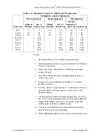
416 drawing (also presented in Table 2-A of this manual). This 
battery plant information must be combined with the 
corresponding data for all other equipment in the office to 
engineer the appropriate aspects of the building. 

The four categories of floor plan data relevant to battery plants 
are listed below. 

Floor Space: Adequate space must be allocated for the battery 
plant footprint and for aisles. 

Floor Load: The building structure must support the intended 
weight per unit floor area, and equipment must be spaced out to 
distribute the load, as necessary. 

Heat Load: The air-conditioning and ventilation system is sized 
to maintain the environment given the heat dissipation of the 
equipment. 

AC Service: The ac distribution system is sized to 
accommodate the current requirements of the powered 
equipment.

Summary of Contents for H569-416

Page 1: ...ologies LINEAGE 2000 600 Ampere 48 Volt ECS Battery Plant Notice Every effort was made to ensure that the information in this document was complete and accurate at the time of printing However information is subject to change 1996 Lucent Technologies All Rights Reserved Printed in U S A ...

Page 2: ...iddle East and Africa 1 3 Asia Pacific Region 1 3 Customer Service 1 4 2 Product Description Plant Specifications 2 1 Typical Battery Plant Description 2 3 Battery Plant Subsystems 2 3 ECS Battery Plant Physical Description 2 4 Introduction 2 4 Rectifier 2 5 Controller 2 6 Batteries 2 6 DC Distribution 2 7 Distribution Bus Bars 2 7 Plant Shunt 2 7 Low Voltage Battery Disconnect Reconnect LVD R Fea...

Page 3: ...roller Options 3 23 Alarm System Interface 3 24 Earthquake Bracing 3 24 Appearance Packages 3 24 Planning 3 26 Floor Plan Data 3 26 Cable Rack and Routing 3 27 Grounding 3 27 Growth 3 27 Ordering 3 27 Coding and Terminology 3 27 J drawings 3 29 T drawings 3 35 SD drawings 3 36 Documentation References 3 37 4 Installation General 4 1 Installation Tools And Test Equipment 4 2 Suggested Installation ...

Page 4: ...ugust 1996 Table of Contents 3 Red LVD OPEN LED Lit 5 5 Yellow LVD FAIL LED Lit 5 5 Blown Fuse on CP5 5 5 Repair and Replacement 5 5 Load Circuit Breaker Replacement 5 6 LVD R Contactor Replacement 5 7 LVD Fuse Board CP5 Replacement 5 8 Spare Parts 5 9 6 Product Warranty ...

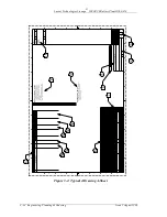
Page 5: ...w Voltage Disconnect Reconnect Contactor K1 2 11 Figure 2 5 ECS DC Distribution Panel Front View 2 12 Figure 2 6 ECS DC Distribution Panel Front Door Removed 2 13 Figure 2 7 Plug In Circuit Breaker Mounting 2 14 Figure 3 1 ECS Appearance Package Option 3 25 Figure 3 2 Typical J Drawing A Sheet 3 34 Figure 4 1 DC Distribution Cable Layout 4 8 Figure 4 2 Typical Floor Mounting Detail 4 9 Figure 4 3 ...

Page 6: ...in Information 3 7 Table 3 C Reserve Capacity 3 8 Table 3 D Field Wiring Specifications 3 18 Table 3 E Lug And Hardware Ordering Codes 3 19 Table 3 F Feeder Current Size 3 22 Table 3 G Minimum Wire Gauge Ampacity All Strings 3 23 Table 4 A Minimum Torque For All Electrical Connections 4 4 Table 4 B Torque and Minimum Yield Strength for Mechanical Connections Using Hex Head Cap Screws 4 5 Table 4 C...

Page 7: ...lutionary Control System ECS Battery Plant and its components such as Controller Rectifier and Battery manuals Each manual contains a technical description of the product which is followed by detailed information on engineering installation operation and maintenance The contents of the documentation package are identified for ordering and reference purposes in Section 3 of this manual The Lineage ...

Page 8: ...ent Technologies equipment is available to customers around the world USA Canada Puerto Rico and the US Virgin Islands On a post sale basis during the Product Warranty period our Technical Support telephone number 1 800 CAL RTAC 1 800 225 7822 provides coverage during normal business hours Product Specialists are available to answer your technical questions and assist in troubleshooting problems F...

Page 9: ...ds Product Repair and Return Repair and return service for Lucent Technologies equipment is available to customers around the world USA Canada Puerto Rico and the US Virgin Islands For information on returning of products for repair customers may call 1 800 255 1402 for assistance Central and South America If you need to return a product for repair your sales representative will be happy to discus...

Page 10: ...ive for information regarding spare parts Figure 1 1 Lineage 2000 ECS Battery Plant Model H569 416 LINEAGE 2000 LVD R FAIL OPEN R E C T 1 R E C T 7 R E C T 2 R E C T 8 R E C T 3 R E C T 9 R E C T 4 R E C T 10 R E C T 5 R E C T 11 R E C T 6 M E T E R C P 2 C P 3 C P 1 D B B A T A B S C P 1 R B R E C T 12 U S E R 1 U S E R 2 U S E R 3 ECS Distribution Panel ECS Controller SR 100 24V Rectifiers Lucen...

Page 11: ...oltage 40 60 Vdc 48 Vdc nominal Float Voltage 47 58 5 Vdc 48 Vdc nominal Plant Current Rating 600 amperes Plant Shunt 1200 amperes maximum at 50 millivolts LVD R Voltage Settings 40 5 or 42 5 Vdc Controller Basic 113B Microprocessor option circuit pack Datalogger circuit pack 48 Volt Distribution 3 panels accommodate up to 21 KS23616 circuit breakers each Rectifier Shelf Assembly Complement 4 maxi...

Page 12: ...maximum temperature by 0 656 C per 100 feet above 1524 meters Framework Type 7 foot Network Bay Frame standard 23 inch relay rack Vertical mounting centers 1 00 inches 25 mm Horizontal mounting centers 22 32 inches 567 mm Dimensions Height 84 inches 2134 mm Width 26 inches 660 mm Depth 18 5 inches 470 mm Depth when equipped with VR batteries 26 inches 660 mm Weight Initial bay equipped with 12 rec...

Page 13: ... of the typical dc battery plant subsystems from the ac input to the dc output These subsystems are defined as follows AC Distribution connects the commercial and or standby ac power sources to the rectifiers within the plant and provides overcurrent protection This subsystem is usually supplied by the customer Rectifiers convert an ac source voltage into the dc voltage level required to charge an...

Page 14: ... 240 Vac 50 60 Hz source It offers a 600 ampere total plant capacity with a nominal 48 Vdc output The ECS battery plant is compatible with all flooded and valve regulated batteries that have a short circuit current rating less than 7 000 amperes In addition the ECS plant is capable of operating in a batteryless mode making it suitable for those applications where battery backup is not necessary or...

Page 15: ...ptional appearance kit Rectifier The Lineage 2000 SR Series rectifiers are designed specifically for applications where small size low weight and ease of installation are of overriding importance The rectifiers utilize a combination of switch mode technology and forced air cooling to achieve a significant reduction in size and weight over conventional ferroresonant rectifiers The plug in connector...

Page 16: ...he Lineage 2000 SR Series rectifier product manual for additional information Controller The ECS controller performs the centralized monitoring control and reporting functions for the ECS battery plant The basic ECS controller can monitor and control up to 12 rectifiers It also provides a single interface point for power alarm and status reporting Two optional expansion circuit packs are available...

Page 17: ...or load circuits are terminated on the discharge return bus Plant Shunt A current shunt is a sensing device which provides a millivolt signal proportional to the current flowing through it The millivolt to ampere ratio of the shunt is the dc resistance of the shunt in milliohms which is thermally stable and accurately known The current shunt in the ECS Battery Plant is connected between the Charge...

Page 18: ...er manual for further details The red LVD OPEN and yellow LVD FAIL LEDs are located on the front side of the dc distribution panel as shown in Figure 2 5 The red LVD OPEN LED on the CP5 Fuse Board is lit whenever the contactor is open during a normal disconnect or in the unlikely event of a contactor failure The LVD sensing circuitry on CP5 is redundant A failure of either voltage detector circuit...

Page 19: ... 2 August 1996 Product Description 2 9 Circuit Breakers The KS23616 circuit breaker is available in 3 5 10 15 20 30 45 and 60 ampere ratings These are plug in rather than screw mounted breakers The 45 and 60 ampere circuit breakers take up two positions on the panel ...

Page 20: ...ription Issue 2 August 1996 Figure 2 3 ECS Distribution Bus Bars To Loads To Loads To Loads LVD Bus Plant Shunt Circuit Breaker Bus Discharge Return Bus Battery Bus LVD R K1 or Strap Charge Return Bus Distribution Bus Negative Rectifier Bus Positive Rectifier Bus To Rect Shelves ...

Page 21: ...ECS Battery Plant H569 416 Issue 2 August 1996 Product Description 2 11 Figure 2 4 Low Voltage Disconnect Reconnect Contactor K1 Battery Bus Auxiliary Switch See Side View LVD Bus LVD R Contactor K1 Front View Side View N04 N03 NC2 NC1 ...

Page 22: ...st 1996 Figure 2 5 ECS DC Distribution Panel Front View LINEAGE 2000 LVD R FAIL OPEN R E C T 1 R E C T 7 R E C T 2 R E C T 8 R E C T 3 R E C T 9 R E C T 4 R E C T 10 R E C T 5 R E C T 11 R E C T 6 M E T E R C P 2 C P 3 C P 1 D B B A T A B S C P 1 R B R E C T 12 U S E R 1 U S E R 2 U S E R 3 Lucent ...

Page 23: ...7 60 60 18 61 40 19 62 62 20 63 42 21 DO NOT EXCEED 300 AMPERE LOAD PER BUS BAR DO NOT EXCEED 300 AMPERE LOAD PER BUS BAR DO NOT EXCEED 300 AMPERE LOAD PER BUS BAR DO NOT EXCEED 300 AMPERE LOAD PER BUS BAR DO NOT EXCEED 300 AMPERE LOAD PER BUS BAR DO NOT EXCEED 300 AMPERE LOAD PER BUS BAR La batterie n est pas deconnectee Risque de choc electrique ou de blessures Ne pas toucher la bourne nue Batte...

Page 24: ...ineage 2000 ECS Battery Plant H569 416 2 14 Product Description Issue 2 August 1996 Figure 2 7 Plug In Circuit Breaker Mounting TERMINAL BLOCK FOR LOAD CONNECTIONS TO LOAD LINE PWB ALARM LOAD NORMALLY OPEN AUXILIARY CONTACT ...

Page 25: ...s account executive This section of the manual is intended to provide guidance for those customers who wish to completely or partially engineer their battery plant The detailed process of engineering a battery plant is described as it progresses through four stages This process is essentially the same for the field modification of an existing battery plant as it is for a new installation The four ...

Page 26: ...mended operating voltage range of the using equipment If the battery plant is used to power different types of equipment it must meet the requirements of each Fill in the load voltage information below The answers to these questions will be used in engineering calculations and equipment selection in the following paragraphs a Recommended operating voltage ______ volts b Minimum steady state voltag...

Page 27: ...AL 48 VOLT systems although any plant voltage is possible by varying the number of cells per string The NOMINAL CELL VOLTAGE of lead acid type batteries is usually defined as 2 volts The actual recommended float voltage of lead acid batteries differs slightly among vendors and varies with chemistry The most common float voltages are 2 17 2 27 and 2 35 volts per cell Nominal 48 volt systems typical...

Page 28: ...g system is provided in the following paragraphs Load Drain and Growth Under normal conditions with a constant load battery plant voltage to the load equipment is essentially constant During an ac power outage however the batteries deliver power and their voltage drops steadily since most types of load equipment do not draw a constant current over their input voltage range Therefore the current dr...

Page 29: ...mation for all load circuits in the initial installation in Table 3 A Use additional sheets as needed As the customer s power needs evolve however load circuits may need to be added and traffic on existing circuits may increase Ultimate List 2 drain should be used to select the initial sizes of load feeder cables and plant discharge capacity since these cannot be readily increased once the plant i...

Page 30: ... Technologies Lineage 2000 ECS Battery Plant H569 416 3 6 Engineering Planning Ordering Issue 2 August 1996 Table 3 A Initial Load Drain Information Load Circuit List 1 Amps List 2 Amps 1 Battery Plant Total ...

Page 31: ... ECS Battery Plant H569 416 Issue 2 August 1996 Engineering Planning Ordering 3 7 Table 3 B Anticipated Future Load Drain Information Load Circuit List 1 Amps List 2 Amps NC C or A 1 Battery Plant Total NC No Change C Changed A Added ...

Page 32: ...mum reserve time below n Minimum battery reserve time ____ hours Battery capacity is usually specified in terms of AMPERE HOURS a measure of energy The ampere hour rating is the product of a constant discharge current and the time to discharge a fully charged battery to a specified end voltage For comparison purposes most vendors of telecommunications batteries specify ampere hour ratings at the 8...

Page 33: ...led EQUALIZE CHARGING For the purposes of this manual the term Equalize is used to indicate boost or equalize charging Refer to the battery manufacturer s recommendations on equalize charging The recharging requirement is determined by customer practices and is usually specified as a maximum time to reach a minimum percent of full capacity for example at least 90 capacity in no more than 24 hours ...

Page 34: ...portional to the magnitude of the recharge current Any voltage drop from the battery plant bus bars to the terminals of each battery string will tend to slow the rate of battery recharge and delay their readiness for future discharges The same cable resistance responsible for voltage drop during recharge creates a voltage drop during discharge as well Voltage drop during discharge can limit the ef...

Page 35: ... larger cables may usually be tapped down to smaller ones to make the actual connections to the bus bars and battery terminals Battery Size versus Voltage Drop The critical requirement for a battery plant is that the input voltage to the load equipment remain within the proper operating range for the prescribed reserve time Constants imposed by the typical 48 volt battery system are the normal bat...

Page 36: ...mb specifies a maximum voltage drop of 0 75 volts in the feeder loop from the dc distribution to the load and back again using the List 2 drain for that circuit as listed in Table 3 B Voltage drop calculation methods are described in paragraph Calculating Voltage Drop Fill in the selected or calculated system voltage drops below v Maximum drop batteries to dc distribution ____ volts w Maximum drop...

Page 37: ...n conductor These two criteria are ampacity and voltage drop Ampacity is the current that may be carried safely without overheating the conductor In relatively low voltage high current systems such as dc distribution voltage drop limitations are often the determining factors in sizing conductors In systems such as ac distribution with relatively high voltage and low current ampacity usually determ...

Page 38: ...dard rating above the ampacity Overcurrent protectors may be sized smaller than this maximum rating In general however protectors should be rated as high as allowable to avoid nuisance tripping due to high load conditions or inrush during start up Lineage 2000 Engineering Specifics The methods used in the paragraph General Engineering Calculations are appropriate for the engineering of any battery...

Page 39: ...g The battery type and minimum size are determined in paragraphs Battery Plant Voltage and Reserve Capacity Many vendors offer families of batteries that cover a wide range of ampere hour capacities Ampere hour capacities of parallel battery strings are added to provide the total reserve capacity of the battery plant Tosupply the necessary reserve several strings of small capacity batteries or one...

Page 40: ...n battery capacity depends on the desired recharge factor See paragraph Charge Capacity and Recharge Time for an explanation of charge capacity and recharge factor Since the charge capacity of the Lineage 2000 ECS battery plant grows in 50 ampere increments with the SR50A 48V rectifier the optimum battery capacity increment may be approximated as follows A hr increment 50 A x reserve time in hours...

Page 41: ...by this paragraph of the product manual This paragraph derives the basic dc power cabling which will be required as part of a complete cable engineering process Lucent Technologies offers cabling engineering services that are separate from battery plant engineering Contact your Lucent Technologies Account Executive for more information on available services Wire type RHW or RHH should be used for ...

Page 42: ...Space inches Crimp Die Required Hardware Lug Provided Hardware Provided 3 50 A Crkt Brkr Single Hole Double Hole 12 AWG 10 AWG 8 AWG 6 AWG 5 8 Red 10 32 Screw Yes Yes 60 100A Crkt Brkr Adapter Double Hole Adapter Double Hole 2 AWG 5 8 Blue 10 32 Nut Screw No Yes 100A Crkt Brkr Single Hole Double Hole 2 AWG 5 8 Brown 1 4 20 Screw No Yes 225A Crkt Brkr Single Hole Double Hole 4 0 AWG 1 Yellow 5 16 1...

Page 43: ...05347857 405348251 406434175 10 10 1 4 1 4 1 4 1 4 1 4 5 16 5 16 5 16 5 16 5 16 5 16 5 8 5 8 5 8 5 8 5 8 5 8 5 8 1 0 1 0 1 0 1 0 1 0 1 0 R5473 Red Red Blue Grey Brown Green Pink Black Black Orange Purple Yellow Available Single Hole Terminal Lugs STR Class B Flex Class 1 WP 91412 List Comcode Bolt Size Die 10 8 8 6 4 2 1 0 2 0 4 0 10 8 8 6 4 2 1 0 2 0 4 0 93 1 74 2 4 53 7 55 10 10 17 58 76 4063381...

Page 44: ... feeder in Table 3 F Use additional sheets as needed Step A Copy List 2 drains for each load feeder from Table 3 B to Table 3 F Step B Calculate the minimum wire size that meets the ampacity requirement based on the List 2 drain for each load feeder Step C List the wire sizes based on ampacity in Table 3 F Step D Calculate the minimum wire size for each load feeder in Table 3 B to meet the voltage...

Page 45: ... Step M Indicate the larger size for each load feeder in the final column Selected Wire Gauge Note Insulation on field wiring conductors should be rated no less than 75 C Wire conductor size determined by the formula above should be no less than allowed by electrical codes for 75 C wire regardless of insulation temperature rating used and the ampacity of the associated protection device In order t...

Page 46: ...age 2000 ECS Battery Plant H569 416 3 22 Engineering Planning Ordering Issue 2 August 1996 Table 3 F Feeder Current Size CIRCUIT NUMBER LIST 2 DRAIN MINIMUM WIRE GAUGE SELECTED WIRE GAUGE BREAKER RATING AMPACITY VOLTAGE DROP 1 ...

Page 47: ...or no If yes specify the disconnect level _____ 40 5 or 42 5 Controller Options The engineering of the ECS controller features involves orderable circuit packs and field movable jumper straps Circuit Packs Circuit pack options for the ECS controller are presented on the H569 416 battery plant drawing Refer to that drawing and to the Controller manual for more information on the availability of opt...

Page 48: ...nd type with the terminal blocks provided on the controller circuit packs as detailed in the Controller Manual Earthquake Bracing The earthquake ratings for the standard ECS battery plant is Zone 4 upper floors per NEBS TR EOP 000063 Appearance Packages An appearance package option is available for the initial and supplementary bays of the ECS battery plant This option is shown in Figure 3 1 It in...

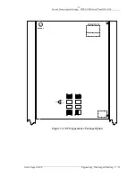
Page 49: ...ng Ordering 3 25 Figure 3 1 ECS Appearance Package Option LINEAGE 2000 LVD R FAIL OPEN R E C T 1 R E C T 7 R E C T 2 R E C T 8 R E C T 3 R E C T 9 R E C T 4 R E C T 10 R E C T 5 R E C T 11 R E C T 6 M E T E R C P 2 C P 3 C P 1 D B B A T A B S C P 1 R B R E C T 12 U S E R 1 U S E R 2 U S E R 3 Lucent ...

Page 50: ...re collectively called Floor Plan Data This information is sometimes published on Floor Plan Data Sheets For the Lineage 2000 ECS Battery Plant complete Floor Plan Data is given on a sheet of the H569 416 drawing also presented in Table 2 A of this manual This battery plant information must be combined with the corresponding data for all other equipment in the office to engineer the appropriate as...

Page 51: ...e selection of protector and wire sizes for load feeders building systems should be designed for ultimate growth Cable rack support and ac distribution cabinets should be sized for the maximum anticipated battery plant capacity Floor space and weight capacity should also account for any increase in battery reserve Ordering Many customers are familiar with Lucent Technologies s drawings diagrams an...

Page 52: ... to each combination of options Instead a MAIN CODE is specified which is followed by a list of identifiably separate options with the quantities for each option The main code number falls into one of three categories J code ED code H code J codes take the form JxxxxxA y and are used to specify main assemblies stand alone products and units that may have multiple applications ED coding of the form...

Page 53: ...etails for engineering planning ordering record keeping installation and repair A thorough understanding of the construction and content of the standard drawings is therefore required for proper error free engineering and ordering of the battery plant The drawings associated with this battery plant should be reviewed completely before preparing an order The generic features of J T and SD drawings ...

Page 54: ...between vintages of the same product Ordering information may or may not change when a J drawing is reissued The drawing issue must agree with the vintage of product available from Lucent Technologies Reissued drawings are sometimes released prior to actual factory availability to provide time for engineering and order preparation Consult your Lucent Technologies Account Executive for assistance w...

Page 55: ...al supplementary lists may be specified for one main list Restrictions on possible combinations of main and supplementary lists are described in the feature descriptions in Table A and or in Engineering Notes see below 5B Ratings The availability for ordering of each List is controlled by the Rating listed in Table A Currently there are two Rating classifications Available AVAIL or no marking and ...

Page 56: ...fine standard symbols used on the assembly views and in the stocklist to indicate stamping and factory packaging methods Additional manufacturing notes are specific to each J drawing All manufacturing notes should be read and understood by engineering as well as installation since they may include important installation details that the engineer must plan for 9 Engineering Notes For engineering th...

Page 57: ... Lineage 2000 ECS Battery Plant H569 416 Issue 2 August 1996 Engineering Planning Ordering 3 33 assembly views clerical error corrections and part number changes The Issue number and date always FOLLOW the list of changes ...

Page 58: ...URNISHED PER THIS DRAWING IS IN ACCORDANCE WITH AT T COMPANY STANDARD XXX XXX XXX LINE LINE LINE NAME NAME NUMBER UGII V4 1 02 22 88 NUMBER 1 1 8 2 2 9 3 3 10 4 4 11 5 5 12 6 13 7 14 CIRCUIT NAME SCHEMATIC WIRING DIAGRAM FIGURE OPT WIRING WIRED REMARKS WIRING PROVIDE IN THE LOCAL CABLE TABLE C WIRING PROVIDED INFORMATION DENOTES NOT REQUIRED BY INSTALLER TABLE D LIST OF ASSOCIATED DRAWINGS DA DA D...

Page 59: ...Change Table on the SD drawing See below As noted earlier there is usually a close correspondence between options defined on the SD and those shown on the T drawing The exact correlation of options and figure numbers between the two drawings is given in Table C Table D gives is an index to the locations of T drawing options on the various sheets of the drawing There is a similar Option Index on th...

Page 60: ... The SD drawing package is usually sectionalized similar to the J drawing as follows A sheets are cover sheets including Title Block Supporting Information Sheet Index Option Index All of this information is similar in format to that on T and J drawings B sheets contain the Functional Schematics FSs C sheets list the Apparatus Figures APP FIGs i e circuit component lists D sheets contain drawing n...

Page 61: ...separate schematic drawings some of which are proprietary and are not generally accessible Documentation References The following documents provide the engineering ordering and installation information for the Lineage 2000 ECS battery plant the ECS controller the Lineage 2000 SR series rectifier and Rectifier Shelf Assembly RSA Plant Assembly and Ordering Drawing H569 416 Controller Assembly and O...

Page 62: ...ircuits A suggested test sequence is also provided to check the integrity of the installation effort Upgrades retrofits and replacement of equipment in the controller rectifier and battery subsystems are covered in their respective manuals The framework rectifier controller and dc distribution subsystems described in Section 2 are factory tested as a system The controller and distribution subsyste...

Page 63: ...ly Power Supply variable from zero to 60 volts dc at 2 amperes Supply should have both coarse and fine output controls i For LVD R option only Six clip leads each capable of carrying 3 amperes Suggested Installation Sequence General Information 1 The plant may be wired with ac from the left side or the right side Typical routing of ac dc and control cabling is shown on the plant assembly drawing H...

Page 64: ...resence of shipping personnel for signs of damage If damaged follow the shipping carrier s procedure for filing a damage claim To ensure personnel safety and equipment protection use appropriate equipment during handling of crates and uncrated equipment Use the equipment weights and dimensions given in Section 2 as a guideline for choosing material handling tools Move crated equipment to an area w...

Page 65: ...n 1 4 inch thick tapped copper bars use No 8 No 10 or 1 4 inch machine screws to minimize applicable torque When larger size screws are required provide captive type steel nuts or reduce torque 8 Torque recommendations are also suitable for all non ferrous fasteners except aluminum 9 Where application permits hex cap screws should be used Table 4 A Minimum Torque For All Electrical Connections Scr...

Page 66: ... 107 190 193 290 410 580 760 1010 Table 4 C Installation Reference Documents Step Procedure Reference Document A Unpacking Handling and Frame Installation H569 416 Drawing and Installation Template C Initial Battery Charge Rectifier Manual D Cable Support and Ground System Job Application Drawings E Controller Setup and LVD Test Controller Manual F AC Wiring Rectifier Installation and Rectifier Te...

Page 67: ... auxiliary ground bus bars as dictated by the job application drawings Step E Controller and LVD Set up Follow the controller set up procedure given in the Controller manual to complete the steps below 1 Enable disable equalize charge set up 2 Enable disable rectifier restart set up 3 Set HV shutdown level s 4 Set BD alarm level 5 Run office alarm wiring 6 Run other controller wiring 7 Set up othe...

Page 68: ...rs across pins 2 and 3 of their respective connectors Refer to the ECS controller manual for acceptance testing procedures for the CP5 circuit pack and the associated LVD R option Step F AC Wiring Rectifier Installation Test Refer to the installation and start up procedure in the Rectifier manual for the following steps Wire AC Set up Plug in Test Before proceeding verify that all rectifier output...

Page 69: ...Cable Layout TO BATTERIES LOAD RETURN LOAD RETURN SYSTEM GROUND BRACKET BATTERY LVD BATTERY BUS BAR DISCH RTN BUS BAR CHG RTN BUS BAR LEFT SIDE VIEW FRONT VIEW RIGHT SIDE VIEW DC DISTRIBUTION DISCH RTN BUS BAR BATTERY STRAP BUS BAR BATTERY BUS BAR PANEL DOOR RIGHT TO LOAD RETURNS TO LOADS DC DISTRIBUTION TO BATTERIES TO LOAD ...

Page 70: ...4 2 Typical Floor Mounting Detail Framework Base 844218784 Hold Down Plate 2 Places 405889254 Floor Anchor Bolt 12 Millimeter Part Number 0003266520 Hilti 4 Places 841628571 Hold Down Washer 4 Places Floor Covering Note Use 3 4 Inch Drill for Floor Anchor Bolts The Required Minimum Drill Depth is 4 Inches ...

Page 71: ... at mounting position 1 primary mounting position then alternate locations 2 and 4 shall be selected as follows 3 94 2 00 18 00 2 00 3 94 2 00 2 00 25 88 1 17 7 25 9 59 3 25 Location 2 If interfering bar at 1 runs perpendicular to equipment lineup Location 3 If interfering bar at 1 runs parallel to equipment lineup Location 4 Permitted only if two reinforcing bars running perpendicular and paralle...

Page 72: ...t H569 416 Issue 2 August 1996 Installation 4 11 Figure 4 4 LVD Fuse Board CP5 Jumper Locations J505 2 GENERAL PATH OF CABLE 4 1 1 1 3 8 P506 P505 2 LVD FUSE BOARD BCB4 CIRCUIT SIDE 3 3 1 1 1 5 P507 P505 1 P508 TB501 12 1 20 P502 40 1 P501 P504 J505 1 ...

Page 73: ...ll a circuit breaker first verify that the circuit breaker is in the OFF position Plug in the circuit breaker and visually verify that the line load and alarm connections are properly mated See Figure 2 7 Remove the knockout from the associated position on the cover Mark the new circuit on the distribution cover label Spare circuit breakers may or may not be provided with the dc distribution panel...

Page 74: ...he plant bus bars Terminate the cables from the dc distribution at each battery string according to the manufacturer s documentation Measure the resistance between the two ends of any battery string to verify that the circuit is open Close the last remaining part of the battery circuit on each string intercell connector Reinsert all fuses in CP5 Fuse Board Match the fuse ratings and positions as i...

Page 75: ...diately due to inrush current when the plant is initially turned on This does not necessarily indicate a fault condition Attemptto close the circuit breaker a second time If the breaker trips again check the wiring to the load circuit Step K Converter Shelf Assembly Follow the Initial Start up and Checkout procedure given in the ECS FPS DC DC Converter Plant manual to complete the steps below 1 Te...

Page 76: ...aker in the OFF position Notify the alarm reporting center that alarms may be received Step C Open the dc distribution cover panel taking care not to disturb any load carrying circuit breakers Step D Locate the intended new breaker position Spare circuit breakers may or may not already be in place on the dc distribution panel as ordered Alternatively spare distribution leads may or may not have be...

Page 77: ...circuit on the distribution cover panel label Step G For safety close the dc distribution front cover before proceeding to the next step Step H Turn on the load circuit breaker If the circuit breaker trips immediately when turned on it may be due to inrush current and does not necessarily indicate a fault condition Attempt to close the circuit breaker a second time If the breaker trips again check...

Page 78: ... red LVD OPEN LED indicates that the disconnect reconnect contactor is open and therefore that batteries are disconnected from the rest of the battery plant The yellow LVD FAIL LED indicates that only one of the two redundant low voltage detectors has directed the contactor to open and that the disconnect circuit may have failed Fuses F1 through F12 are also located on the CP5 LVD Fuse Board and p...

Page 79: ... off manually but this may affect service to the load If a breaker has tripped off the overcurrent problem should be cleared before restoring power to the load by resetting the breaker See paragraph Troubleshooting for information on tripped breakers Troubleshooting Table 5 A provides a list of observable trouble conditions their possible causes and the necessary corrective action for each cause T...

Page 80: ...AD RECTIFIER 10 F 1 F 13 F 7 F 2 F 14 F 8 F 3 F 15 F 9 F 4 F 16 F 10 F 5 F 17 1 1 3 A 0 5 A F 11 F 6 F 18 F 19 F 20 F 21 SPARE FUSES 1 1 3 A MINOR FUSE ALARMS MINOR FUSE ALARMS MAJOR FUSE ALARMS MAJOR FUSE ALARMS 1 1 3 A 2A F 12 REG LEAD RECTIFIER 5 REG LEAD RECTIFIER 11 REG LEAD RECTIFIER 6 REG LEAD RECTIFIER 12 113B METER CP2 AND CP3 CP1 RECTIFIER INTERFACE POWER RECTIFIER CP1 INTERFACE POWER AL...

Page 81: ...reaker except when the trip is suspected to be caused by inrush current during equipment start up Table 5 A Troubleshooting Observed Condition Probable Cause Procedure Controller Red or yellow LEDs lit No LEDs or Display lit Meter inaccuracy Office alarms issued False alarms issued Blown fuse on LVD Fuse board See Troubleshooting in Controller Manual Rectifier Red or yellow LEDs lit No LEDs or Dis...

Page 82: ...ng circuits have failed The CP5 circuit pack must be replaced per procedure LVD Fuse Board CP5 Replacement below Yellow LVD FAIL LED Lit The Yellow LVD FAIL LED indicates that one or both of the LVD circuits has attempted to open the contactor but the contactor is closed This may occur in two situations 1 The plant voltage is right at the disconnect level and is within tolerances of the redundant ...

Page 83: ...lty breaker is in fact still closed the load equipment which it powers must be shut down so that no current flows through the breaker Step E Unplug the faulty breaker from the printed wiring board Step F Switch the new circuit breaker to the OFF position before plugging it in Step G Plug in the new breaker ensuring that line load and alarm connectors are properly mated See Figure 2 7 Step H Remove...

Page 84: ...THE CONTACTOR IS OPEN the rectifiers are carrying the load off battery with excess capacity available for charging the batteries battery string s are at a voltage below the rectifier voltage in a state of partial or complete discharge LVD OPEN LED is lit on the distribution front panel The following equipment is required socket wrench with insulated handle 1 2 inch socket Procedure Refer to Figure...

Page 85: ...tion panel 2 Unplug the following connectors from the LVD Fuse Board CP5 Leave the cables dressed P502 from J502 P506 from J506 P501 from J501 P504 from J504 TB501 from J501 3 Remove the 5 mounting screws 4 Unplug P508 from J508 connector Leave the cable dressed 5 Set jumpers J505 1 and J505 2 on replacement LVD Fuse Board CP5 per H569 416 drawing for desired disconnect voltage 6 Reconnect P508 an...

Page 86: ...recommended spares information on the H569 416 drawing Rectifiers and fans LVD Fuse Board CP5 Fuses F1 to F18 Load Circuit Breakers CB1 to CB63 Controller Circuit Packs e g 113B CU Refer to the Controller manual for details on spare controller circuit packs In addition to these items any piece part may be ordered that is identified in the assembly views and stocklist on the H569 416 drawing When o...

Page 87: ...ms Seller to the extent permitted does hereby assign to Customer the warranties given to Seller by its Vendor of such Vendor Items such assignment to be effective upon Customer s acceptance of such Vendor Items With respect to Vendor items recommended by Seller in its specifications for which the Vendor s warranty cannot be assigned to Customer or if assigned less than Sixty 60 days remain of the ...

Page 88: ...ins that the Product is not readily returnable for repair Seller will repair the Product at Customer s site With respect to Cable and Wire Products manufactured by Seller which Seller elects to repair but which are not readily returnable for repair whether or not installed by Seller Seller at its option may repair the cable and Wire Products at Customer s site D If Seller has elected to repair or ...

Page 89: ...e traveling and related expenses G Seller makes no warranty with respect to defective conditions or nonconformities resulting from actions of anyone other than Seller or its subcontractors caused by any of the following modifications misuse neglect accident or abuse improper wiring repairing splicing alteration installation storage or maintenance use in a manner not in accordance with Seller s or ...

Page 90: ...Lucent Technologies Lineage 2000 ECS Battery Plant H569 416 6 4 Product Warranty Issue 2 August 1996 Copyright 1996 Lucent Technologies All Rights Reserved Printed in U S A ...

Reviews: