


Lucent Technologies Lineage
®
2000 ECS Battery Plant H569-416
Issue 2 August 1996
List of Figures 1
List of Figures
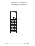
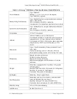
Figure 1-1: Lineage 2000 ECS Battery Plant
(Model H569-416)
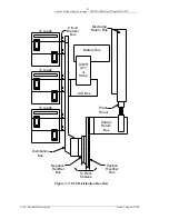
Figure 2-1: Block Diagram of Typical Battery Plant
Figure 2-2: Typical ECS Battery Plant System Block
Diagram 2
Figure 2-3: ECS Distribution Bus Bars
Figure 2-4: Low Voltage Disconnect/Reconnect
Contactor (K1)
Figure 2-5: ECS DC Distribution Panel (Front View)
Figure 2-6: ECS DC Distribution Panel (Front Door
Removed) 2
Figure 2-7: Plug-In Circuit Breaker Mounting
Figure 3-1: ECS Appearance Package Option
Figure 3-2: Typical J-Drawing A-Sheet
Figure 4-1: DC Distribution Cable Layout
Figure 4-2: Typical Floor Mounting Detail
Figure 4-3: Floor Mounting Template
Figure 4-4: LVD/Fuse Board (CP5) Jumper Locations
Figure 5-1: Fuse Designation and Function for
LVD/Fuse Board (CP5)