Lucent Technologies Lineage
®
2000 ECS Battery Plant H569-416
2 - 8 Product Description
Issue 2 August 1996
separate the load circuits from the rectifiers, thus enabling the
rectifiers to begin powering the load as soon as ac power is
restored.
The LVD/R option consists of the LVD/R Contactor, circuitry
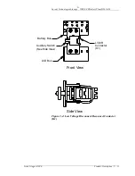
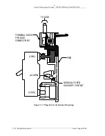
on the CP5 Fuse Board and associated wiring. Figure 2-4 is a
pictorial of the contactor (K1). The LVD circuit on CP5
monitors the plant charge bus voltage, designated RB. When the
RB voltage drops below a preset level, a comparator circuit on
the CP5 Fuse Board senses the low voltage condition and
removes power to the contactor. This opens the connection
between the battery buses and LVD bus, disconnecting the
batteries from the rectifiers and the load. The user has a choice
of disconnect threshold voltages (40.5 and 42.5 volts).
When the contactor is open and the rectifiers are not delivering
power, the controller is also unpowered. In this state, the
controller displays and LEDs are extinguished and various
alarms are issued to the alarm reporting center. (See the
Lineage
®
2000 Controller manual for further details.)
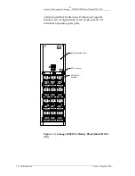
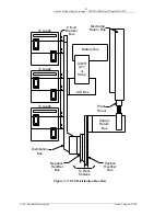
The red “LVD OPEN” and yellow “LVD FAIL” LEDs are
located on the front side of the dc distribution panel as shown in
Figure 2-5. The red “LVD OPEN” LED on the CP5 Fuse Board
is lit whenever the contactor is open, during a normal disconnect
or in the unlikely event of a contactor failure. The LVD sensing
circuitry on CP5 is redundant. A failure of either voltage detector
circuit lights the yellow “LVD FAIL” LED, but the contactor
will stay closed. A Fuse Alarm Minor (MNF) is issued when a
LVD circuit fails, lighting a yellow LED on the controller front
panel and sending Power Minor (PMN) alarms to the alarm
reporting center.
Once the contactor opens it remains open until the RB voltage
again exceeds the set threshold voltage. Voltage does not return
until ac power is restored and the rectifiers restart. Once the
LVD circuit is energized, the LVD/R contactor closes the
circuit, allowing the batteries to be charged.
Distribution
Panels/Circuit
Breakers
Distribution Panels: The battery plant is equipped with three
distribution panels. Panels can accommodate up to 21 KS23616
circuit breakers each. Each bus bar in the panel is rated at 200
amperes in a 25°C ambient temperature. The unique plug-in
panel and circuit breaker design makes installation and growth a
snap.

