


Issue 5 November 2000
363-206-208
Powering, Verification, and Circuit Pack Installation for the DDM-2000 OC-12 Multiplexer
Lucent Technologies - Proprietary
See Notice on first page
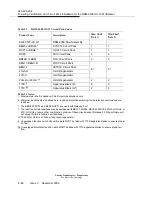
Notes:
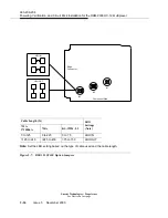
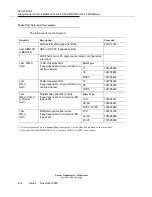
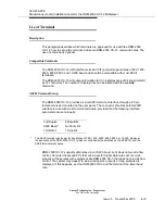
1. The switches are set by moving the slide toward the desired position.
2. If the invalid switch setting is selected, the FAULT LED lights and an alarm is generated.
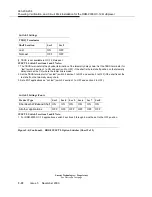
Note:
Controls line coding and frame format for both DS1 input and output.
* Factory default
* Factory default
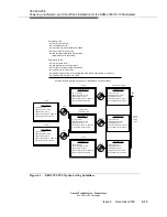
Figure 5-8.
BBF2B/BBF4 TGS Option Switches for OC-12 Multiplexer (Sheet 1 of 2)
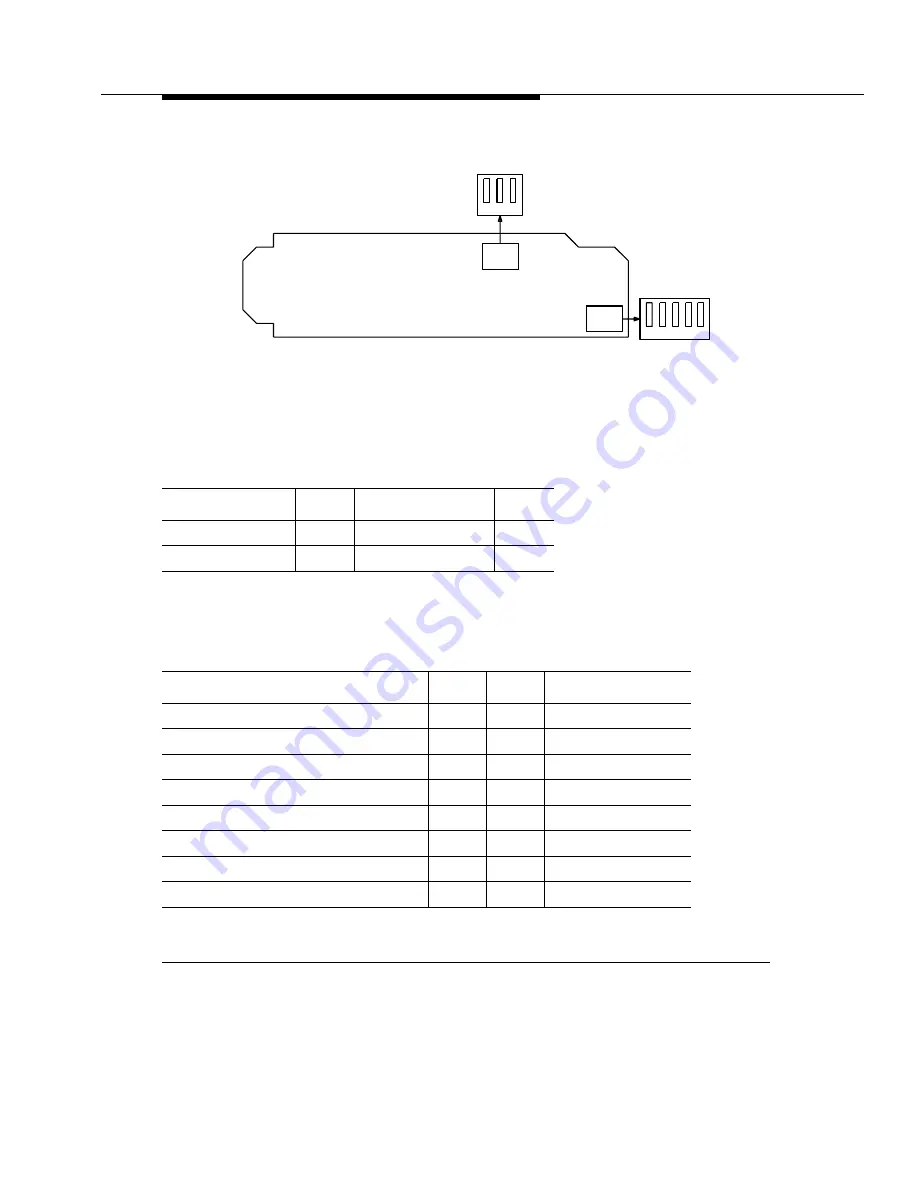
Switch 1 Settings
DS1 Line Coding
Sec 1
DS1 Frame Format
Sec 2
AMI*
ON
SF*
ON
B8ZS
OFF
ESF
OFF
Switch 1 Settings
Timing Mode
Sec 3
Sec 4
Sec 5 (DS1 Output)
Free Running
ON
ON
OFF
DS1 External, MULT OUT Mode*
OFF
ON
OFF
Line Timing
OFF
OFF
OFF
Line Timing, SYNC OUT Mode
OFF
OFF
ON
DS1 External, SYNC OUT Mode
OFF
ON
ON
(Invalid)
ON
OFF
ON
(Invalid)
ON
OFF
OFF
(Invalid)
ON
ON
ON
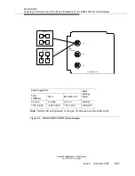
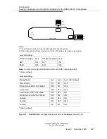
Connector
Edge
S2
OFF
ON
3
2
1
5
S1
OFF
ON
Component Side
4
3
2
1
Summary of Contents for DDM-2000 OC-12
Page 4: ......
Page 370: ...GL 22 Issue 5 June 2000 363 206 208 Glossary ...
Page 382: ...363 206 208 Index 1 ...


