


Issue 5 November 2000
363-206-208
Stand-Alone (Local) Installation Tests for the DDM-2000 OC-12 Multiplexer
Lucent Technologies - Proprietary
See Notice on first page
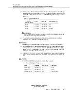
b. Refer to Table 6-2 on page 6-31 and Table 6-3 on page 6-32 and connect
the voltmeter positive lead to the alarm wire for a specific alarm bit and
connect the negative lead as described above, 0 volts will be measured.
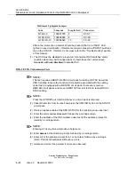
(4) Issue the command
test-tlm-par
(TEST TELEMETRY PARALLEL).
(5) At the mode prompt, enter the “mode identifier” for the desired alarm bit as
determined from Table 6-2 on page 6-31 and Table 6-3 on page 6-32.
An individual telemetry point or miscellaneous discrete point can be tested by
entering
cr
,
mj
,
mn
,
pmn
,
aco
,
clf
,
inc
,
ne
,
fe1
,
fe2
,
fe3
,
fe4
,
fe5
,
fe6
, or
output 1-15
at the mode prompt.
NOTE:
output 11
through
output 15
are not available with Releases 5 and 7 soft-
ware.
(6) At the repeat prompt enter a number
1
through
10
.
NOTE:
Issuing the TEST TELEMETRY command will activate the alarm bit for 20 sec-
onds. The number selected for this prompt will determine the number of times
that this bit will be activated for 20 seconds and then stay off for 20 seconds.
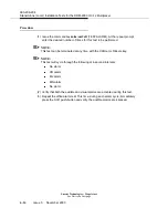
(7) Either:
a. Verify that the maintenance center has observed the alarm bit. If the
alarm bit indication is not observed by the maintenance center, See Table
6-1 on page 6-27 and Table 6-2 on page 6-31 for wiring connection infor-
mation.
or
b. The voltmeter should read 48 volts. If the alarm bit indication is not
observed at the office alarm interface, verify alarm telemetry wiring. Refer
to Table 6-2 on page 6-31 and Table 6-3 on page 6-32 for wiring connec-
tion information.
(8) Verify that the correct SID indication is activated, (that is, the SID indication
should be the same as the DDM-2000 OC-12’s shelf number).
(9) Repeat the parallel telemetry test for each individual telemetry point.
Summary of Contents for DDM-2000 OC-12
Page 4: ......
Page 370: ...GL 22 Issue 5 June 2000 363 206 208 Glossary ...
Page 382: ...363 206 208 Index 1 ...


