


Issue 5 November 2000
363-206-208
Powering, Verification, and Circuit Pack Installation for the DDM-2000 OC-12 Multiplexer
Lucent Technologies - Proprietary
See Notice on first page
Switch 2 sections 1 through 6
are used to control the identification of the DCC for open systems
interconnection (OSI) interworking. For a given optical span, the network elements that terminate
on each side of the optical span must have their
network side / user side
parameters set to oppo-
site values to avoid an inconsistent DCC switches alarm. Switch 2
Sec 1
thru
Sec 6
are set to OFF
for the Network Side and ON for the User Side of network elements in an optical span.
NOTE:
Release 2 multiplexer software requires the BCP1 to be a series S2:3 or later, Release 3
software requires the BCP1 to be series S2:4 or later.
NOTE:
Release 1 Multiplexer software and Release 1 and 2 Regenerator software, does not con-
tain the OSI feature and therefore Switch 2 should be set to the factory default values
shown in the following table:
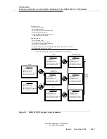
For Release 2 systems, refer to Figure 5-6 on page 5-25 on the following page for an example sys-
tem configuration, noting the opposite values set at each terminating node. The effected switch
settings are highlighted in bold type. Set Switch 2 settings according to work order or office
records using this example as a guide. Switch 2
Sec 7
and
Sec 8
must be set to ON.
NOTE:
OSI settings on DDM-2000 OC-3 shelves are located on the BBG7 OHCTL.
For Release 3 Ring systems, since OLIUs are connected main-b-1 of one node to main-b-2 of
another node, the Switch 2 factory default settings shown in the above table will be correct for
each DDM-2000 OC-12 shelf in the ring. However, for Release 3.1 Rings systems containing OC-
3 optical extensions, Switch 2
Sec 3
thru
Sec 6
must be set to values opposite than the values of
the corresponding OSI settings on the BBG7 circuit packs of the DDM-2000 OC-3 terminating
nodes. Switch 2
Sec 7
and
Sec 8
must be set to ON.
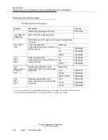
For all Multiplexer and Regenerator Releases, Switch 3
Sec 1
thru
Sec 8
are set to ON.
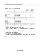
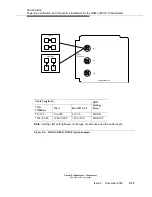
Figure 5-5 (Continued). BCP1 OHCTL Option Switches (Sheet 2 of 2)
Switch 2 Settings for Linear Applications
main-a Sec 1
main-b Sec 2
fn-a
Sec 3
fn-b
Sec 4
fn-c
Sec 5
fn-d
Sec 6
Sec 7
Sec 8
OFF
ON
OFF
OFF
OFF
OFF
ON
ON
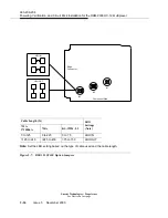
Switch 2 Settings for Ring Applications
main-b-2
Sec 1
main-b-1
Sec 2
fn-a
Sec 3
fn-b
Sec 4
fn-c
Sec 5
fn-d
Sec 6
Sec 7
Sec 8
OFF
ON
OFF
OFF
OFF
OFF
ON
ON
Summary of Contents for DDM-2000 OC-12
Page 4: ......
Page 370: ...GL 22 Issue 5 June 2000 363 206 208 Glossary ...
Page 382: ...363 206 208 Index 1 ...


