


34
been carefully done at the Factory and no further attempt should normally be required.
e. 2.5 Mc. IF Amplifier.- Connect a 21.4 mc marker signal to control grid of V-606 and tune
L-608, L-610 and L-611 for a maximum indication of the Signal Strength meter, M-101, on
the front panel. Eventually readjust also L-606 and L-607 for a maximum indication on the
Signal Strength meter, M-101, on the front panel.
“Slave” 40 Kc. IF Channel Alignment
d. 40 Kc. Band-Pass Filter. Adjustment of L-602 and L-603.— Set the function switch to
AM 40 Kc. Connect a 2.5 Mc. centered sweep generator between control grid of V-604 and
ground on the nuvistor socket mounting strap nut. Connect the scope to control grid of V-
605. Adjust L-602 and L-603 for maximum gain centered around the 2.5 Mc marker. The
18.9 Mc. pip, generated by the second local oscillator V-603, can be seen on the scope on the
high frequency side of the response curve, well beyond the filter passband.. This pip may be
identified by removing the 18.9 Mc. oscillator and observing the pip disappear.
Note: The adjustment of the L-602 and L-603 coils that form the 40-Kc. Band-Pass filter has
been carefully done at the Factory and no further attempt should normally be required.
e. 2.5 Mc. IF Amplifier.- Connect a 21.4 mc marker signal to control grid of V-601 and tune
L-604 for a maximum indication of the Signal Strength meter, M-101, on the front panel.
Eventually readjust also L-602 and L-603 for a maximum indication on the Signal Strength
meter, M-101, on the front panel.
3. LOCAL OSCILLATOR ADJUSTMENTS.
a. Local Oscillator Adjustment, “Master” RF Tuner only.
The only adjustment necessary in the local oscillator is to make the tuning dial read properly.
This section may be disregarded if the dial is reading correctly. If a tube has been replaced
and an error is noted, it may be corrected by adjustment of C-229. This adjustment should be
made with a signal generator of high accuracy at 60 Mc.
The high-frequency end of the dial is controlled by the location of C-230 on the end inductor
L-210, The correct adjustment is made at the factory and should not require readjustment in
the field.
Summary of Contents for G-187
Page 7: ...7 Figure 1 1 Model G 187 Special Purpose Receiver Front View...
Page 9: ...9 Table 1 2 Semiconductor and Tube Complement...
Page 10: ...10 Table 1 2 Semiconductor and Tube Complement continued...
Page 14: ...14 Fig 2 1 Block Diagram Model G 187 Receiver...
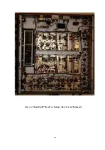
Page 44: ...44 Fig 4 1 Model G 187 Receiver Top View Cover Removed...
Page 45: ...45 Fig 4 2 Model G 187 Receiver Bottom View Covers Removed...
Page 46: ...46 Fig 4 3 Model G 187 Receiver Rear View...
Page 47: ...47 Fig 4 4 Model G 187 Receiver Panoramic Top View Cover Removed...
Page 48: ...48 Fig 4 5 Model G 187 Receiver Panoramic Top View Left Side Cover Removed...
Page 49: ...49 Fig 4 6 Model G 187 Receiver Panoramic Top View Right Side Cover Removed...
Page 50: ...50 Fig 4 7 Model G 187 Receiver Panoramic Bottom View Covers Removed...
Page 51: ...51 Fig 4 8 Model G 187 Receiver Panoramic Bottom View Left Side Covers Removed...
Page 52: ...52 Fig 4 9 Model G 187 Receiver Panoramic Bottom View Right Side Covers Removed...
Page 53: ...53 Table 4 2 Model G 187 Receiver Component Boards Lists...
Page 54: ...54 Fig 4 10 Model G 187 Receiver Large Component Board...
Page 56: ...56 Fig 4 14 Model G 187 Receiver Master Slave RF Tuners Top View...
Page 57: ...57 Fig 4 15 Model G 187 Receiver Master Slave Tuners Bottom View Covers Removed...
Page 58: ...58 Fig 4 16 Model G 187 Receiver Master Slave Tuners Panoramic Bottom View Covers Removed...
Page 59: ...59 Fig 4 17 Model G 187 Receiver Master RF Tuner Bottom View Cover Removed...
Page 60: ...60 Fig 4 18 Model G 187 Receiver Slave RF Tuner Bottom View Cover Removed...
Page 67: ...67 Fig 5 1 Model G 187 Receiver Schematic Diagram Master RF Tuner...
Page 68: ...68 Fig 5 2 Model G 187 Receiver Schematic Diagram Slave RF Tuner...
Page 71: ...71 Fig 5 5 Model G 187 Receiver Schematic Diagram Main Chassis Circuits...
Page 72: ...72 Fig 5 6 Model G 187 Receiver Schematic Diagram Mainframe...
Page 73: ...73 Fig 5 7 Model G 187 Receiver Schematic Diagram Power Supply Circuits...
Page 74: ...74 Fig 5 8 Model G 187 Receiver Schematic Diagram Various Details...