


33
nut. Set the sweep generator to produce a peak scope deflection of 0.25 Volts. Adjust T-305
(primary) and T-306 (secondary) for a symmetrical response curve centered around 21.4 Mc.
The shape of the response curve should be flat-topped or slightly double-peaked.
f. Second IF
amplifier, adjustment of T-303 and T-304.— Replace V-301. Disconnect the
cable connected to J-202 on the RF chassis. Connect the scope to first limiter grid (pin 1 of V-
303). Solder a 10 Ohm resistor between pin 1 of V-301 and ground of the tube socket
mounting strap nut. Solder a 200 Ohm resistor to pin #1. Connect the sweep generator
between the 200 Ohm resistor and ground on the grounded lead of the 10 Ohm resistor. Set
the sweep generator output as required to produce a peak scope deflection of 0.25 Volts.
Adjust T-303 (primary) and T-304 (secondary) for a symmetrical response curve centered
around 21.4 Mc. The response shape should be flat-topped or slightly double-peaked.
After the adjustment is completed, remove the 10 and the 200 Ohm resistors.
g. First IF Amplifier, adjustment of T-301 and T-302.- Reconnect the cable to J-202. Install
the IF bottom cover and tighten all the mounting screws. Connect the scope to first limiter
grid (pin 1 of V-303). Connect the sweep generator to TP-202 (on the RF chassis) and ground
on one of the trimmer capacitor studs. Set the sweep generator output as required to produce
0.25 Volts peak scope deflection. Adjust T-301 (primary) and T-302 (secondary) for a
symmetrical response centered around 21.4 Mc.
The response shape should be very nearly flat-topped.
“Master” 40 Kc. IF Channel Alignment
d. 40 Kc. Band-Pass Filter. Adjustment of L-606 and L-607.— Set the function switch to
AM 40 Kc. Connect a 2.5 Mc. centered sweep generator between control grid of V-609 and
ground on the nuvistor socket mounting strap nut. Connect the scope to control grid of V-
610. Adjust L-606 and L-607 for maximum gain centered around the 2.5 Mc marker. The
18.9 Mc. pip, generated by the second local oscillator V-608, can be seen on the scope on the
high frequency side of the response curve, well beyond the filter passband.. This pip may be
identified by removing the 18.9 Mc. oscillator and observing the pip disappear.
Note: The adjustment of the L-606 and L-607 coils that form the 40-Kc. Band-Pass filter has
Summary of Contents for G-187
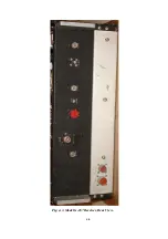
Page 7: ...7 Figure 1 1 Model G 187 Special Purpose Receiver Front View...
Page 9: ...9 Table 1 2 Semiconductor and Tube Complement...
Page 10: ...10 Table 1 2 Semiconductor and Tube Complement continued...
Page 14: ...14 Fig 2 1 Block Diagram Model G 187 Receiver...
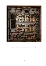
Page 44: ...44 Fig 4 1 Model G 187 Receiver Top View Cover Removed...
Page 45: ...45 Fig 4 2 Model G 187 Receiver Bottom View Covers Removed...
Page 46: ...46 Fig 4 3 Model G 187 Receiver Rear View...
Page 47: ...47 Fig 4 4 Model G 187 Receiver Panoramic Top View Cover Removed...
Page 48: ...48 Fig 4 5 Model G 187 Receiver Panoramic Top View Left Side Cover Removed...
Page 49: ...49 Fig 4 6 Model G 187 Receiver Panoramic Top View Right Side Cover Removed...
Page 50: ...50 Fig 4 7 Model G 187 Receiver Panoramic Bottom View Covers Removed...
Page 51: ...51 Fig 4 8 Model G 187 Receiver Panoramic Bottom View Left Side Covers Removed...
Page 52: ...52 Fig 4 9 Model G 187 Receiver Panoramic Bottom View Right Side Covers Removed...
Page 53: ...53 Table 4 2 Model G 187 Receiver Component Boards Lists...
Page 54: ...54 Fig 4 10 Model G 187 Receiver Large Component Board...
Page 56: ...56 Fig 4 14 Model G 187 Receiver Master Slave RF Tuners Top View...
Page 57: ...57 Fig 4 15 Model G 187 Receiver Master Slave Tuners Bottom View Covers Removed...
Page 58: ...58 Fig 4 16 Model G 187 Receiver Master Slave Tuners Panoramic Bottom View Covers Removed...
Page 59: ...59 Fig 4 17 Model G 187 Receiver Master RF Tuner Bottom View Cover Removed...
Page 60: ...60 Fig 4 18 Model G 187 Receiver Slave RF Tuner Bottom View Cover Removed...
Page 67: ...67 Fig 5 1 Model G 187 Receiver Schematic Diagram Master RF Tuner...
Page 68: ...68 Fig 5 2 Model G 187 Receiver Schematic Diagram Slave RF Tuner...
Page 71: ...71 Fig 5 5 Model G 187 Receiver Schematic Diagram Main Chassis Circuits...
Page 72: ...72 Fig 5 6 Model G 187 Receiver Schematic Diagram Mainframe...
Page 73: ...73 Fig 5 7 Model G 187 Receiver Schematic Diagram Power Supply Circuits...
Page 74: ...74 Fig 5 8 Model G 187 Receiver Schematic Diagram Various Details...