RCI-1502 HRT Tele Boom Manual
Fully retract the boom. Extend the payout wire slightly and note the direction of
rotation of the large gear wheel for an extending boom. Relea se the payout
wire and allow it to retract to its' fu
lly retracted positio n. Turn the large
aluminium gear, by hand, in the opposite direction to that noted fo
r an
extending boom, until the gear sto ps. Turn the gear in the opposite direction
(i.e. as if for extending) for ¾ of a
turn or three clicks of the clutch. Safely
extend the boom to full exten sion ensur ing continuous operation of the gear
wheel and potentiomete r. Fully retrac t the boom and again check operation.
Refit the recoil drum cover and ensure all mounting nuts are tight.
Route the cable carefully from the recoil drum back around the boom pivot to
the cabin. Fix the cable to the boom and turret using adequate fixings ensuring
that the cable is n ot pinched or stretched as the boom moves through its full
luffing arc. Only connect the cable to the Display Unit when finished welding.
Notes:
The slip-rings in the
LSI-Robway
recoil drum are designed for use
with
LSI-Robway
Anti-2-block systems and are not for resistive or
inductive circuits such as lights or bells. If you have a particular
application that you feel may be applicable to the slip-ring facility,
please contact
LSI-Robway
for further advice.
Please note also that high tensile booms require proper welding
procedure specifications. Obtain specialist assistance in these cases.
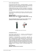
Recoil drum and typical installation at the boom base section
Load Sensor (Dynamometer/Tensiometer Type)
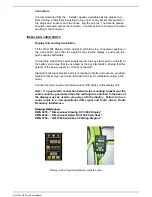
Please Note:
Remove tensiometers during dragline and piling operations. Refer to Section 1.
“Important Safety Notice” – Special Note for Tensiometer Installation & Use.
Summary of Contents for RCI-1502 HRT
Page 2: ......
Page 4: ......
Page 6: ......
Page 8: ......
Page 14: ......
Page 22: ......
Page 44: ......
Page 52: ......
Page 56: ......
Page 58: ......
Page 59: ...Appendix 8 1 Data Logging on RCI Systems ...
Page 60: ......
Page 66: ...Data Logging on RCI Systems Example Lift Cycles ...
Page 71: ...Appendix 8 2 Drawings ...
Page 72: ......
Page 73: ......
Page 74: ......
Page 76: ......
Page 77: ...APPROVED BY TOL 0 0 0 1 2 3 4 55 26 2 0 7 2 8 9 1 1 1 1 0 7 5 6 2 ...
Page 79: ...APPROVED BY TOL 0 0 0 1 22 3 4 5 6 0 22 2 1 7 8 98 1 7 8 98 7 8 98 7 8 98 1 0 9 8 3 6 8 3 ...
Page 80: ... APPROVED BY 0 1 2 22 3 3 3 TOL 4 4 23 4 232 22 3 242 4 2 32 2 3516 7 8 7 7 9 2 3 42 4 2 ...
Page 81: ... APPROVED BY 0 1 2 22 3 3 3 TOL 4 4 23 4 232 22 5 0 42 4 2 3617 8 9 8 8 2 ...
Page 82: ......
Page 83: ......
Page 87: ......
Page 88: ......
Page 89: ......
Page 90: ......
Page 91: ......
Page 92: ......
Page 93: ......
Page 94: ......
Page 95: ......
Page 96: ......
Page 97: ......
Page 98: ......
Page 99: ......
Page 100: ......
Page 101: ......
Page 103: ......
Page 104: ......
Page 105: ......
Page 106: ......
Page 107: ......
Page 108: ......
Page 109: ......


