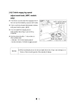

3 - 59
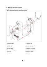
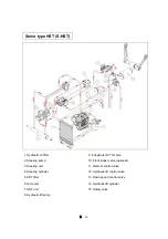
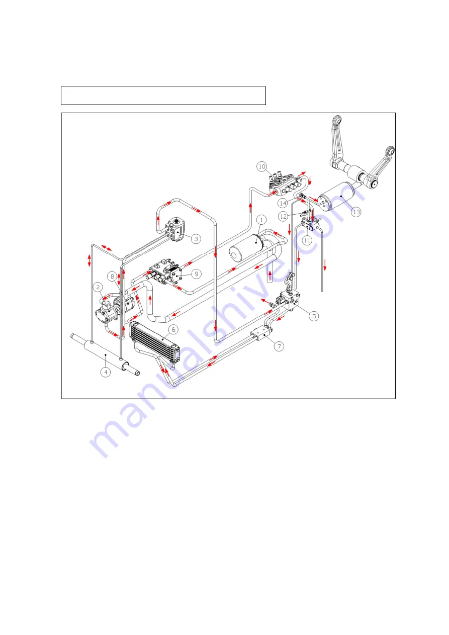
(7) Hydraulic System Diagram
1. Hydraulic oil filter
2. Steering pump
3. Steering unit
4. Steering cylinder
5. Independent PTO valve
6. Oil cooler
7. Cooler valve
8. Hydraulic lift pump
9. Front loader valve (optional)
10. Remote control valve
11. Hydraulic lift control valve
12. Down speed control valve
13. Hydraulic lift cylinder
14. Safety valve
MEC, Mechanical with synchro-shuttle
Summary of Contents for MT342
Page 1: ...LS TRACTOR OPERATOR S MANUAL MT342 MT347 MT352 MT357 Stage...
Page 2: ......
Page 46: ...1 32 2 9 6 11 3 1 Roll Bar 5 10 7 8 4 12 13 14 16 18 17 10...
Page 62: ...1 48...
Page 76: ...2 14...
Page 180: ...4 42...
Page 248: ...5 68...
Page 258: ...7 2 Unit mm Roll bar type Front tires 9 5 16 6PR Rear tires 13 6 24 8PR...
Page 263: ......
Page 264: ...P NO 52132436 05 DATE 20220000...