- Instruction Manual for ESS R050096 -
8
Name
Port
SN
Description
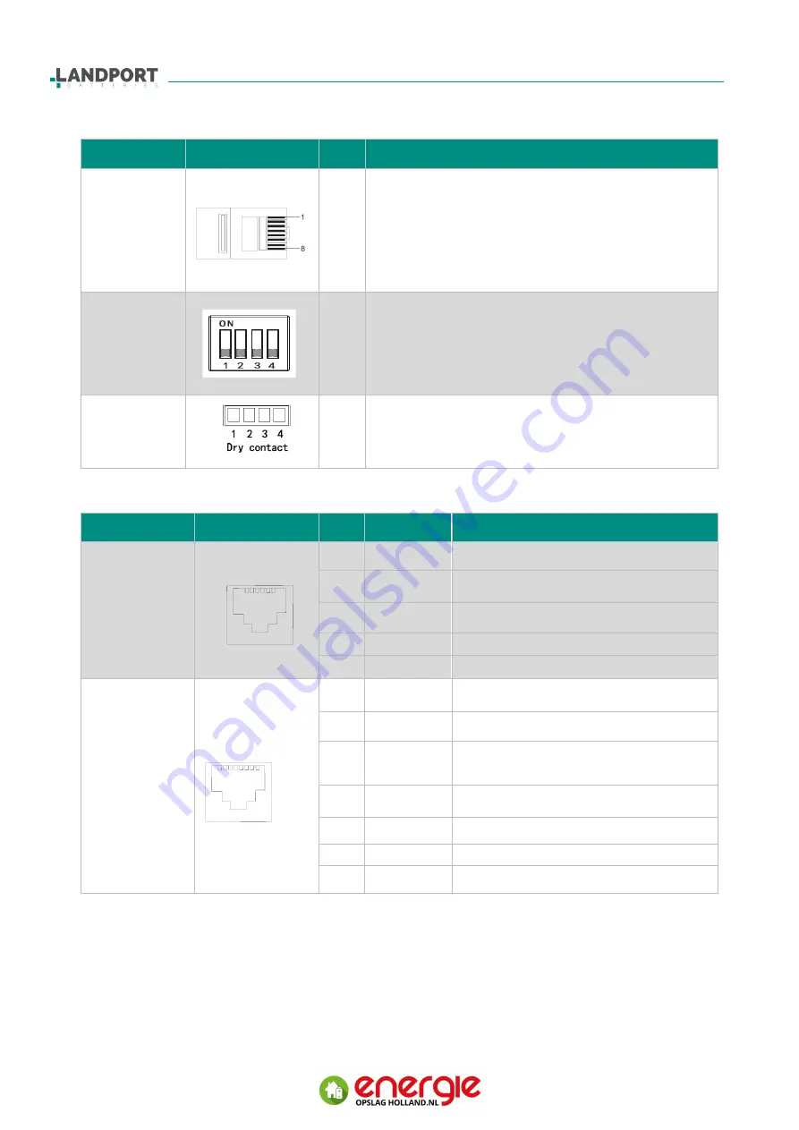
CAN Bus
Terminator
RJ45-8P8C
2-3
A120ohmresistorin1- 2 pin for parallel CAN
communication is needed to terminate the line.
When multiple battery boxes are combined for
CAN communication, an 8- PIN terminator with an
120 ohm resistor is inserted in the last CAN
communication interfaces for parallel CAN
communication termination resistors.
DIP switch
1-4
The dipswitch sets the module address and the
operating mode. The "ON" side indicates "1" and
the other side indicates "0"
For detailed description of the DIP switch settings,
refer to Section 4.1.
Dry contact
1-4
For connection of the cabinet start button boot line
cable.
Name
Port
Pin
Function
Description
RS485 Port
1
RS485B
RS485 communication line B
2
RS485A
RS485 communication line A
3
NC
4-5
NC
6
GND
RS485 communication signal ground
CAN Bus Port
1
CANL
CAN communication line L
2
CANH
CAN communication line H
3
CANLR
Communication Cable L
(Built-in 120Ω termination resistor)
4-5
NC
6
GND
CAN communication signal ground
7
NC
8
NC
7 8
1 2 3 4 5 6
RJ45
1 2 3 4 5 6
RJ11


