- Instruction Manual for ESS R050096 -
7
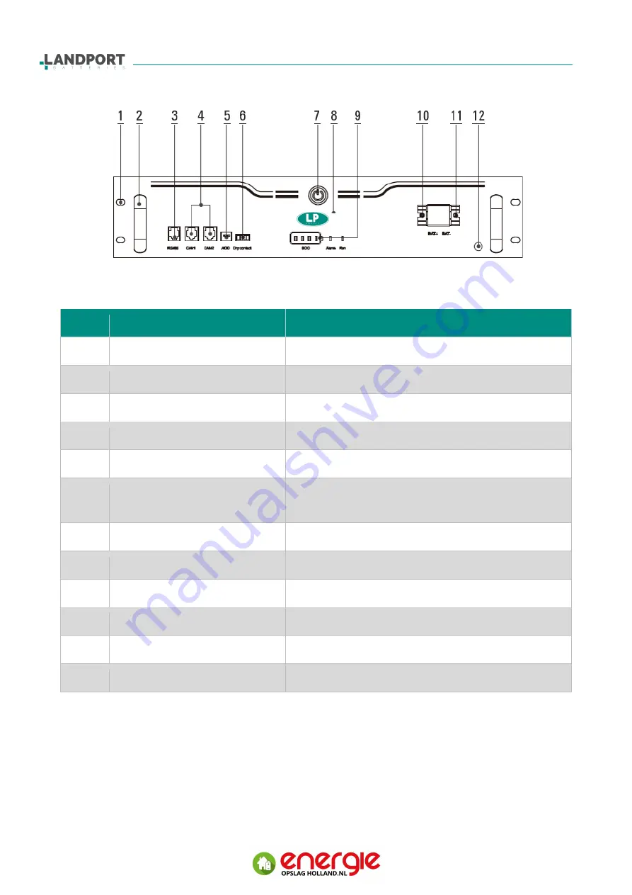
Picture 2-4 Appearance of the battery box
Item
Features & Indicators
Description
1
Mounting slot
To mount onto the rack with screws
2
Handles
3
RS485 communication port
RS485 communication interface (RJ45-6P)
4
CAN communication port
CAN communication interface (RJ45-8P)
5
ADD switcher
DIP Switch
6
Dry node
Dry node interface for battery pack output
(Reserve)
7
On/off button
Press to switch Battery pack on/off mode
8
Brand logo
Logo of manufacturer
9
State indicator
Indicating capacity and error status
10
Output Interface (Po)
Positive interface for power output
11
Output Interface (Negative -)
Negative interface for power output
12
Grounding hole
To battery pack


