- Instruction Manual for ESS R050096 -
6
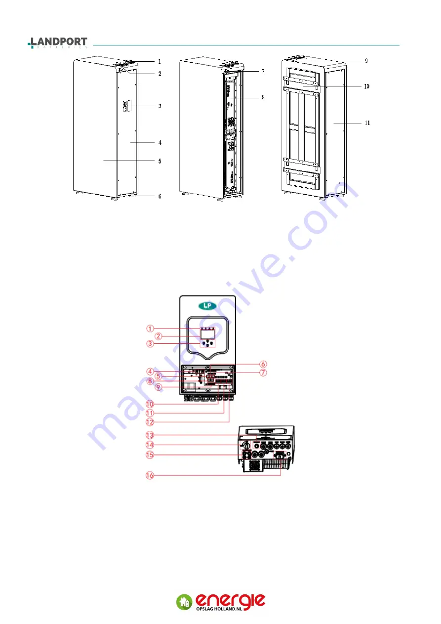
Picture 2-2 Appearance of the Battery Cabinet
(
1
)
Positive and negative terminal
(
2
)
Communication terminal
(
3
)
Battery display window
(
4
)
Right side door
(
5
)
Battery cabinet
(
6
)
Cabinet foot
(
7
)
POWER button
(
8
)
Battery box
(
9
)
Earth point
(
10
)
Back bracket
(
11
)
Left side door
Picture 2-3 Appearance of the inverter
(
1
)
Inverter indicators
(
2
)
LCD display
(
3
)
Function buttons
(
4
)
Battery input connectors
(
5
)
Rs485 port
(
6
)
CAN port
(
7
)
DRMs port
(
8
)
Parallel port
(
9
)
Function port
(
10
)
Generator input
(
11
)
Load
(
12
)
Grid
(
13
)
Power on/off button
(
14
)
DC Switch
(
15
)
PV input with 2 MPPT
(
16
)
WIFI interface


