background image

52

key again. A dashed line ex-
tends from the first waypoint to
the second, showing the first
leg of the route. Continue mov-
ing the cursor and saving way-
points until all of the waypoints
in the route have been selected.
Press the CLR key when you’re
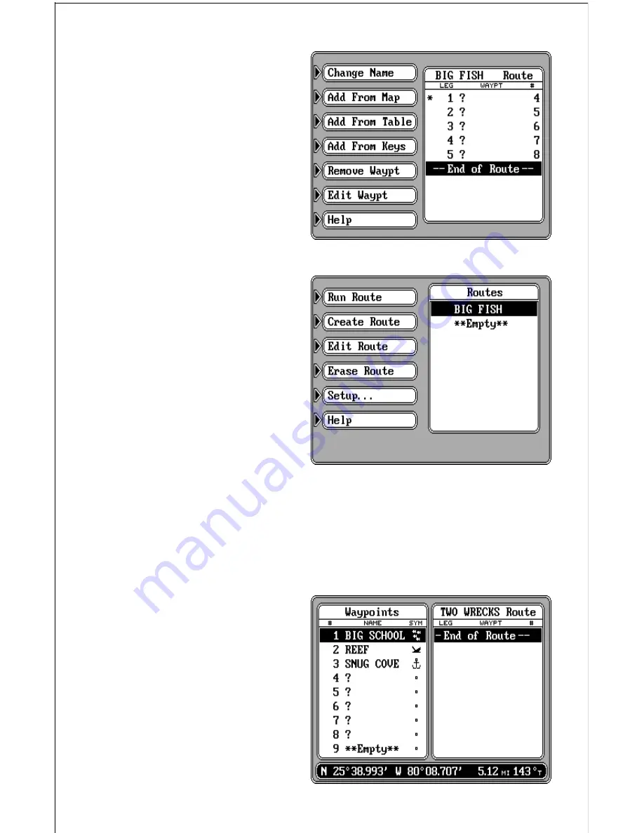
finished. A screen similar to the
one at right appears.

The waypoints used in this route
appear on the right side of the
screen. In this example route,
we saved five waypoints, so
there are five “legs” on the route.
Question marks appear for the
name on all of the waypoints,
since you can’t name the way-
points while entering them from
the map. If you wish to change
anything about the waypoint,
i.e. name, position, or icon, see
the “Edit Waypoint” section. The
waypoint’s number appears on
the far right side of the screen.
This is it’s number in the waypoint list. All of the waypoints that are saved
are added to the waypoint list, no matter how you save them. If the route
shown on the list is the way you want it, simply press the ENT key to save
it. The unit returns to the route menu with your new route at the top of the
list as shown above.

Add From Table
To create a route from the list of
waypoints, first name the route
as shown previously. You
should see the screen at right
after naming the route. Now
press the key next to the “Add
From Table” label. The screen
shown at the top of the next
page appears.

Summary of Contents for GlobalMap 2000

Page 1: ...INSTALLATION AND OPERATION INSTRUCTIONS GlobalMap 2000 TM...

Page 2: ...ntage of all available navigation tools when trav elling to a waypoint but will also visually check to make certain a clear safe path to the waypoint is always available The operating and storage temp...

Page 3: ...ATION STEERING DISPLAYS 28 MAP SCREEN 29 MAPPING OPTIONS 32 NORTH UP COURSE UP 32 MAP NAMES 33 AREA FILL 33 CARTRIDGE SWITCH 34 C MAP SETUP 35 CURSOR 35 PLOTTER TRAIL 36 EVENT MARKER 38 NAVIGATION SCR...

Page 4: ...wrance Maplink cartridge reader Position information can come from any Loran C or GPS receiver via the industry standard NMEA interface or directly from a Lowrance GPS module DGPS capability is also i...

Page 5: ...thicker than 1 2 you ll need the FM 2 in dash mounting bracket accessory Make certain there is clearance behind the dash for the unit and there is enough room to tighten the bolts on both sides Once...

Page 6: ...er to the red lead as close to the power source as possible For example if you have to extend the power cable to the battery or power buss attach one end of the fuse holder directly to the battery or...

Page 7: ...connector on the mapping unit s cable This sends navigation data directly to the mapping unit without using any NMEA input You can if desired use either NMEA output to drive another device while usin...

Page 8: ...000 so accessory switches aren t necessary Any other manufacturer s accessory will need to be connected directly to 12 volt power through it s own fuse Note Do not connect the power wires from any bea...

Page 9: ...DGPS BEACON RECEIVER SAM ST MAPLINK SAM 50HPD DGPS DUAL FREQUENCY INTERFACE GLOBALMAP 2000 TO 12 VDC TO 12 VDC TO 12 VDC TO 192 KHZ TRANSDUCER TO 50 KHZ TRANSDUCER TO SPEED TEMP SENSOR TO 12 VDC WHITE...

Page 10: ...8 LOWRANCE LOWRANCE GPS MODULE DGPS BEACON RECEIVER MAPLINK GLOBALMAP 2000 TO 12 VDC TO 12 VDC WHITE GREEN WHITE RED BLACK GREEN RED BLACK POWER CABLE...

Page 11: ...9 LOWRANCE LOWRANCE GPS MODULE SAM ST MAPLINK GLOBALMAP 2000 TO 12 VDC TO 192 KHZ TRANSDUCER TO SPEED TEMP SENSOR TO 12 VDC...

Page 12: ...0183 version 2 0 interface This is a shielded balanced line interface Do not use the shield on these wires Trim the shield back away from the splice when you attach wires from another device to the ma...

Page 13: ...AP 2000 RECEIVING NMEA 0183 VERSION 1 5 DATA FROM ANOTHER DEVICE OTHER DEVICE S NMEA 0183 VERSION 1 5 OUTPUT CABLE GREEN WIRE GLOBALMAP 2000 NMEA CABLE OTHER DEVICE S NMEA 0183 VERSION 1 5 INPUT CABLE...

Page 14: ...A CABLE OTHER DEVICE RECEIVE WIRES TRANSMIT WIRES GLOBALMAP 2000 SEND AND RECEIVE NMEA 0183 VERSION 2 0 DATA GLOBALMAP 2000 NMEA CABLE Remember undernocircumstancesshouldtheshieldsontheGlobalMap s wir...

Page 15: ...tings label Press the key next to the Select NMEA label The screen shown at right appears Now press the key next to the Select NMEA 0183 label Finally press the key next to the Exit label The LMS 350...

Page 16: ...r the differential DGPS beacon receiver Note You can also use the diagram on pages 7 or 8 if you re using a Lowrance DGPS receiver To connect the beacon receiver attach a twisted pair cable from the b...

Page 17: ...ule to receive the signals fromthesatellites itmustnotbe obstructed An ideallocation ison a cabin roof or deck The gunnels also make a good location Attaching the pole mounting adapter let you install...

Page 18: ...asket and down the hole Place the module on the gasket Slide the cleats onto each end of the module and using the cleats as templates mark four holes for 5 mm 10 mounting screws Drill the holes then r...

Page 19: ...ntingadapterandalignthefourthreadedholesinthe module with the holes in the pole mounting adapter Using the four stainless steel 5 mm screws and lock washers supplied with the LGC 1 attach the pole mou...

Page 20: ...45 USA only MAPLINK TheGlobalMap2000hasaninternal background mapthatcoversalmost the whole world It shows southern Canada all of the continental United States and Mexico at a higher resolution than ot...

Page 21: ...digital navigation screen CARTRIDGE ADAPTER SMARTMAP CARTRIDGE MAPLINK Notice You can attach up to seven Maplinks to the GlobalMap 2000 This lets you use different maps without having to unplug one a...

Page 22: ...press this key CENTER Centers the map around your present position CURSOR Pressing this key activates the moveable cursor lines WAYPT ROUTE This key lets you save or recall a waypoint or route WAYPOI...

Page 23: ...akecertainalloftheacces sories are connected to the mapping unit ThenpresstheONkey Thescreen at right appears Press the CLR key to erasethisscreen NowpresstheMENU key three times Each time you press t...

Page 24: ...ving data then check all wiring connections SAMmodulesstartworkingatthesametimethemappingunitisturnedon The mapping unit also automatically sends both versions of NMEA 0183 data at power on Initializa...

Page 25: ...example to change the latitude to 41 18 023 first press the 4 keywhilethe 3 inthelatitudeis flashing Thischangesthe 3 to a 4 It also moves one digit to the right making the number 5 start flashing No...

Page 26: ...use COLD START When the GlobalMap 2000 is turned on for the first time out of the box it automatically sends a cold start message to the Lowrance GPS module You can also send a cold start message to t...

Page 27: ...m of the screen To exit this screen press the CLR key DGPS SETUP Someareashaveinstalledorareplanningtoinstalldifferentialtransmitters that send correction data to a special receiver The U S Coast Guar...

Page 28: ...y and bit rates set Most DGPS transmitters have different frequencies and bit rates The GlobalMap 2000 needs to know the frequency of the transmitter and its bit ratethatyouwillbeusingwiththeLowrance...

Page 29: ...e time and date show beneath the status Beneath the date display is the fix status The fix quality has a range from 0 9 9 is the best 0 the worst As the fix number decreases the position s jitter incr...

Page 30: ...rate Rate signal to noise ratio SNR signal strength Sig and age status AGE At the very bottom of the screen are the DGPS statistics DGPS An OK in this field means that the DGPS corrections for that sa...

Page 31: ...le with a cross on the screen The latitude lon gitude of your present position shows at the bottom of the screen Each time you switch to this screen it centers your present position and the map on the...

Page 32: ...shown on this screen The box in the upper right corner of the screen is a combination navigation display A compass shows your current course over ground at the top of the box This is the direction you...

Page 33: ...ext to it This means you need to steer to the right to get back on the correct course The distance from your present position to the course line appears at the bottom of this box This is called cross...

Page 34: ...e top of the screen no matter what your actualheadingis The Center modekeepsyourpresentposi tion at the center of the screen and moves the map around it Note TheGlobalMap2000won toperateinthecourseupo...

Page 35: ...above steps Map Names Major cities highways rivers lakes states and more are shown on the Lowrance background map and Lowrance cartridges C MAP cartridges and background map also show the names of ma...

Page 36: ...e versa You must use the C MAP background with a C MAP cartridge and the Lowrance background map with the Lowrance inland modules The default setting is the Lowrance background map and modules To swit...

Page 37: ...or press the key next to the More label to return to the mapping setup menu CURSOR The GlobalMap 2000 has moveable cursor lines that let you pinpoint locations on the map create waypoints routes and...

Page 38: ...n data showing in the digital boxes A dotted line appears on the map from your present position to the cursor showing the shortest most direct line to the cursor position A box with the letter S appea...

Page 39: ...you ve taken then press the key next to the Trail Display label This turns the plot trail off but it s still kept in memory If you turn the trail display on again it will show your entire plot trail...

Page 40: ...nd every tenth mile travelled Plot Trail Trail Type The plot trail shown on the display can be changed from a solid line to a dotted line using the Trail Type selection on the Trail Plotter menu Simpl...

Page 41: ...This makes the map s cursor lines appear on the display Now move the lines to the desired positiononthedisplaybypress ing the arrow keys When it s at the desired location press the EVENT MARKER key t...

Page 42: ...sired event markers show ingthatyouwishtoerase press theEVENTMARKERkey then press the key next to the DEL ALL IN VIEW label A mes sageappears warningyouthat this will erase all of the event markers th...

Page 43: ...navigation data from our present position on the map Pressing the NAV key at the bottomoftheunitwhilethenavi gation screen is displayed changes all of the boxes shown at the bottom of the display Of...

Page 44: ...rately steer the boat to a waypoint The numbers immediately below the C D I are the C D I range in miles This gives you an idea of how far off course you are For example if the arrow is halfway betwee...

Page 45: ...done we ll use the Navigation screen as an example To customize the Navigation screen first make certain it is showing by pressing the NAV key Next press the MENU key two times Now press the key next...

Page 46: ...nishedcustomizingthe screen simply press the CLR screen This erases the arrow from the display and locks in your changes These changes are held in memory and are saved even if power is turned off Sinc...

Page 47: ...plays the way pointonthemapandstoresthe positioninthewaypointlist The number shown on the map is the number assigned to it on the waypoint list See below for more information on storing waypoints Wayp...

Page 48: ...aypt label You can also change anything on an existing saved waypoint by using the Edit Waypt label Editing a Waypoint After you ve pressed the key next to the Save Present Save Cursor or Edit Waypt l...

Page 49: ...ld Now enter the desired latitude If you need to change the latitude from north to south press the key next to the S label Afteryou vemade the desired changes to the lati tude pressthedownarrowkey to...

Page 50: ...rns to the mapping screen It draws a S with a box around it showingyourpositionwhenyou recalled the waypoint See the screenbelow Adottedlineextendsfromthisboxtotherecalledwaypoint Thislineistheshortes...

Page 51: ...ap You can show all waypoints or turn them off show only the symbols names or number or any combination of these To change the waypoint dis play firstpresstheMENUkey then press the key next to the Map...

Page 52: ...ATING A ROUTE Name a Route To create a route first press the WAYPT ROUTE key Next press the key next to the Routes label The screen shown below appears This menu lets you create a route edit an existi...

Page 53: ...at order when making the route Add From Map To create a route using the cur sor on the map press the key next to the Add From Map label A screen similar to the one at right appears To save the first w...

Page 54: ...e map If you wish to change anything about the waypoint i e name position or icon see the EditWaypoint section The waypoint s number appears on the far right side of the screen This is it s number in...

Page 55: ...t then press the ENT key The waypoint shows at the top of the list under the route name on the right side of the screen When all of the waypoints have been added to the route press the CLR key This re...

Page 56: ...nged To do this first press the arrow keys to move the black box to the waypoint that you wish to change Next press the key adjacent to the Edit Waypt label on the Edit Route menu shown above The Edit...

Page 57: ...press the key next to the Routes label The screen shown above appears Now move the black box to the desired route using the arrow keys then press the key next to the Run Route label The screen shown...

Page 58: ...ocation It then automatically switches to the next waypoint in the route showing navigation to the second waypoint location This process repeats until the route is completed When you arrive at the las...

Page 59: ...ou turn an alarmonoroff Thebottomhalf letsyouadjust thearrival cross track error and anchor radius alarms The default for all alarmsis off Toturnanalarm on simply press the key next to the alarm s lab...

Page 60: ...k error is 3 4 mile If the XTE alarm is set to 1 mile the alarm sounds shown by an imaginary line on the screen at right letting you know how far off course your present po sition is This alarm is adj...

Page 61: ...wotimes Now press the key next to the Units of Measure label The screen shown at right appears Simply press the key next to thelabelthatyouwishtochange until the check mark in that la bel moves to the...

Page 62: ...ar on this screen Whenyoufirstenterthisscreen the contrast is ready for adjust ment To change another fea tureonthisscreen simplypress the left or right arrow key to highlight the desired feature Then...

Page 63: ...erboard Information label Thescreenshownatright appears Your position time and date when the Man Overboard key was pressed shows at the top of the screen If you wish to save your present position in s...

Page 64: ...to a waypoint using the Waypoint Recall feature at any time however this stops the GlobalMap 2000 from navigating to the Man Overboard position Remember saving the victim is the primary goal Try all...

Page 65: ...een by the GlobalMap 2000 If the display datum is different fromthesourcedatum theGlobalMap2000 translates thesourcedatum to the displayed one This lets you display a map using any datum on the list o...

Page 66: ...inuously add the change to all position displays This makes it more closely match the datum used by the chart For this reason you should be careful when entering the PCF offset This offset is saved in...

Page 67: ...speed over ground There are three settings off low and high When the unit is first turned on or is preset the filter is turned off To set the filter press the MENU key three times The screen shown ab...

Page 68: ...ELECTION AND CALIBRATION When a sonar module with speed and temperature capabilities such as the SAM ST is connected to the GlobalMap 2000 speed through water water temperature and a distance log can...

Page 69: ...e has a ten degree range as its default For example in the screen shown above the temperaturegraphrangeisfrom70to80degrees atendegreerange You can change this range to 2 or 4 degrees by pressing the k...

Page 70: ...change so the illustrations in this manual do not show the frequency on the sonar screens SONAR TABLE OF CONTENTS SONAR OPERATION 69 SONAR KEY 69 AUTOMATIC 70 SENSITIVITY 70 RANGE 71 UPPER AND LOWER L...

Page 71: ...utomatic mode at first As you become familiar with the information shown on the screen try adjusting some of the featuressuchaszoom upperandlowerlimits sensitivity andmore You ll soon find the sonar f...

Page 72: ...he Man box Now press the CLR key The menus disappear and the full screen sonar shows The letters MAN at the top of the screen signifies that the unit is inthemanualmode Youcannowmakeanychangesoradjust...

Page 73: ...appear change the range back to the original scale The sensitivity level should be close to ideal If there s too much noise on the screen random echoes or if you still can t see enough detail bump th...

Page 74: ...5 20 30 40 60 100 150 200 300 400 600 1000 and 1500 meters 0 1 2 2 5 7 10 15 20 30 40 60 80 100 150 200 300 500 and 800 fathoms UPPER AND LOWER LIMITS When the manual mode is on the range s upper and...

Page 75: ...the upper and lower limits press the CLR key to erase the sonar menus ZOOM Enlargingor zooming thepictureisacommonmethodusedtoshowsmall detail and fish signals Although changing the upper and lower l...

Page 76: ...oom while in the manual mode first press the MENU key the press the key adjacent tothe SonarControls label Now press the key next to the More label A screen simi lar to the one above appears Now press...

Page 77: ...l This freezes the screenuntilyoupressthesame key again You can press the CLR key while the chart is stopped seeing a full screen sonar if desired The word STOP appears at the bottom of the screen whe...

Page 78: ...ce clutter This doesn t show when the FishI D featureison Onlythebottomandstructureattachedtothebottom along with fish symbols appear when the Fish I D feature is on If the unit is in the manual mode...

Page 79: ...strength of echoes is by using the Grayline feature This feature paints gray on targets that are stronger than a preset value This lets you see the difference between a hard and soft bottom For examp...

Page 80: ...ppears as shown above Press the key next to the right arrow in the chart speed menu to increase it Press the key adjacent to the left arrow in the menu to decrease the speed The box in the menu has a...

Page 81: ...the key next to the Shallow Depth Alarm ON OFF label This moves the check box from OFF to ON and turns the alarm on Thedefaultsettingfortheshallowalarmis10feetand100feetforthedeep alarm If you need t...

Page 82: ...to move the end of the bar to the desired depth When you re finished press the CLR key to exit this menu Zone Alarm Bar If you wish to leave the zone alarm bar on the display at all times press the M...

Page 83: ...seen on and near the top of the display This noise is caused by many things including tiny plant and animal life wave action and boat wakes When the unit is first turned on or after it s reset both A...

Page 84: ...ress the key adjacent to the Sonar Controls label Now pressthekeynexttothe More label until the Digital Sonar menu appears as shown at right Press the key adjacent to that label The menu shown below a...

Page 85: ...ectedbythekeeloffset feature The chart always shows the distance from the transducer s face To adjust the keel offset press the MENU key repeatedly until the Keel Offset menu appears as shown above No...

Page 86: ...have all of the items shown on this page If you are missing any of the items please call our special toll free number 1 800 324 1353 A RECORDED MESSAGE will request the following information Please h...

Page 87: ...uct THIS REPAIR REPLACEMENT OR REFUND AS JUST DESCRIBED IS THE EXCLUSIVE REMEDY AVAILABLE TO YOU AGAINST US FOR ANY DEFECT MALFUNCTION OR NON CONFORMITY CONCERN ING THE PRODUCT OR FOR ANY LOSS OR DAMA...

Page 88: ...ions of this License Agreement We reserve the right to terminate this license if you violate any aspect of this License Agreement You are responsible for using official government charts and prudent n...

Page 89: ...OT UNDER ANY CIRCUMSTANCES BE LIABLE TO ANYONE FOR ANY SPECIAL CONSEQUENTIAL INCIDENTAL OR OTHER INDIRECT DAMAGE OF ANY KIND Some states do not allow the exclusion or limitation of incidental or conse...

Page 90: ...erifica tion 3 Write a brief note detailing the problem you re having with the unit Please include your name address and daytime telephone number 4 Please include payment for non warranty repairs Chec...

Page 91: ...transducers please contact 1 Your local marine dealer Most quality dealers that handle marine electronic equipment should be able to assist you with these items Consult your local telephone directory...

Page 92: ...age 85 inside this manual for complete warranty details If your unit fails and the failure is not covered by the original warranty Lowrance has a flat rate repair policy that covers your unit and acce...

Reviews: