background image

53

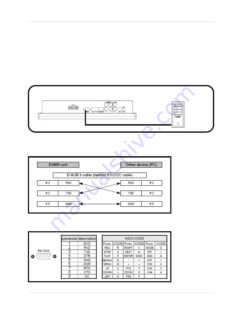
Connecting to a PC using the Serial Port - Appendix #7

Connecting to a PC using the Serial Port - Appendix #7

The Observation System can be connected directly to a PC COM Port by using the Serial Port 
located on the back of the system.

• To connect DVR to a PC, users must use a twisted RS232 cable (See below).

• The RS232 settings (baudrate/ parity/ length/ stop bit) are NOT adjustable. The transmission 

baudrate is 19200bps, length 8 bits, stop bit 1, and the parity is none. ASCII-CODE is 1 BYTE. 

OBSERVATION SYSTEM

PC (Not Included)

Twisted RS232 Cable Configuration

RS232 Port Diagram

Summary of Contents for L15LD400 series

Page 1: ...LOREX Technology Inc www lorexcctv com 15 LCD COLOR OBSERVATION SYSTEM With Built In 4 Channel Triplex Digital Video Recorder and 4 Night Vision CCD Cameras Instruction Manual English Version 1 0 MODEL L15LD400 Series ...

Page 2: ... SHOCK HAZARD DO NOT EXPOSE THIS UNIT TO RAIN OR MOISTURE CAUTION TO PREVENT ELECTRIC SHOCK MATCH WIDE BLADE OF PLUG TO WIDE SLOT FULLY INSERT Thank you for purchasing the L15LD400 Series Observation System Lorex is committed to providing our customers with a high quality reliable security product The L15LD400 Series observation system is one of the most sophisticated video security systems on the...

Page 3: ... cord and if its appearance indicates damage or deteriorated insulation have it replaced by your service technician 7 Power Cord Protection Power supply cords should be routed so that they are not likely to be walked on or pinched by items placed upon or against them paying particular attention to cords at plugs convenience receptacles and the point where they exit from the video product 8 Ventila...

Page 4: ...r can prevent fire electric shock or other hazards 16 Safety Check Upon completion of any service or repairs to this video product ask the service technician to perform safety checks recommended by the manufacturer to determine that the video product is in safe operating condition 17 Wall or Ceiling Mounting The cameras provided with this system should be mounted to a wall or ceiling only as instr...

Page 5: ...cted z Consult the dealer or an experienced radio or television technician for assistance LOREX TECHNOLOGY INC http www lorexcctv com NOTE This equipment has been certified and found to comply with the limits regulated by FCC EMC and LVD Therefore it is designated to provide reasonable protection against interference and will not cause interference with other appliance usage However it is imperati...

Page 6: ...ewing over the internet MJPEG video compression USB Device port for Firmware Upgrade Backup and Image Transfer HDD cradle easy to remove upgrade archive 160GB HDD Designed for Surveillance Hard Drive is specifically designed for optimal performance in the commercial video security applications Cameras Color CCD image sensor 12 IR LEDs provides effective night vision range of 30ft 10m Day Night mod...

Page 7: ...ding Mode Indicators 22 Function Icons 22 HDD Status 22 Display Modes 23 25 Accessing the Onscreen Setup Menu 23 Single Channel and QUAD Display Modes 23 Sequence Display Mode 24 PIP Display Mode 24 Zoom Mode 25 PTZ Pan Tilt Zoom Focus Controls 25 Recording Mode 26 27 Playback 28 31 Starting Playback Mode 28 Stopping Playback Mode 29 Search Mode 29 Percent Search 30 Time Date Search 30 Event Searc...

Page 8: ...SETUP 43 RS232C SETUP 44 BACKUP 44 USB BACKUP SUBMENU 44 Data Backup 45 FIRMWARE UPGRADE 45 Troubleshooting 46 Observation System Specifications Appendix 1 47 Monitor Specifications 47 DVR Specifications 47 MC7521 Camera Specifications Appendix 2 48 Full Connectivity Diagram Appendix 3 49 Connecting a Slave Spot Out Monitor Appendix 4 50 Connecting Motion Alarm Device Appendix 5 51 Connecting PTZ ...

Page 9: ...COMPLETE SYSTEM INCLUDING ALL COMPONENTS SHOWN ABOVE 1 x REMOTE CONTROL 2 x AA BATTERIES 1 x 10 ETHERNET CABLE 4 x 60 FT 18M EXTENSION CABLES 4 x CAMERAS 4 x METAL STANDS 1 x POWER ADAPToR LCD DVR COMBO UNIT WITH INSTALLED 160 GB HDD 1 x HARDWARE MANUAL 1 x SOFTWARE MANUAL 1 x QUICK START GUIDE 1 x SOFTWARE CD 1 x 4 SPLITTER CAMERA POWER ADAPTOR ...

Page 10: ...ntly displayed camera 1x Zoom Use the direction buttons or mouse and move to the area to be enlarged P T Enters PTZ Pan Tilt Zoom control mode A PTZ type camera not included is required to use the PTZ Functions 2 MENU Enters the System Menu and Setup 3 ESC Exits the System Menu and Setup 4 BUTTONS Adjusts the System Menu and Setup values 5 LCD MONITOR POWER BUTTON Turns the LCD Monitor Power ON OF...

Page 11: ...HDD HDD access LED indicated when activity is taking place on the system Hard drive 8 0 9 BUTTONS Switches the full screen view between channels 1 4 Numbers 0 9 are used to enter the System Password 9 SEARCH MODE BUTTONS SEARCH Enters search mode search through previously recorded data Search by percentage date time or the event list MODE Switches between full and split screen displays 1 2 3 4 5 6...

Page 12: ...the playback PLAY Plays back the recorded data REW Fast Rewind of the playback STEP Playback step by step frame by frame FF Fast Forward of the playback 11 DIRECTION ARROWS ENTER DIRECTION ARROWS Moves the mouse cursor and navigates within the System Menu ENTER Confirms the selected options in the System Menu 1 2 3 4 5 6 8 9 10 11 7 ...

Page 13: ...emovable Hard Drive 2 DRIVE BAY LOCK Locking mechanism for the removable drive 3 USB BACKUP PORT Connect a USB memory stick or USB HDD for data backup 4 DEVICE PORT Connect to a PC for firmware upgrade 5 USB MOUSE PORT Connection port for a USB Mouse alternate control for the System 1 2 3 4 5 ...

Page 14: ...ces and for direct connection to PTZ cameras 4 sensor inputs and 1 relay output 4 ETHERNET Connects the System to a network router or other Ethernet Device 5 CH 1 4 BNC Camera inputs for Channels 1 4 6 MONITOR SPOT OUT PORTS MONITOR Connection to a slave monitor SPOT Connection to monitor using SPOT OUT 7 PS 2 MOUSE PORT Connection for a PS 2 mouse 8 POWER INPUT PORT Connection for the DC Power In...

Page 15: ...ystem setup ENTER BUTTON Applies a configuration change in Menu Mode SEARCH BUTTON Enters the Search Menu ZOOM Zooms in on the current image NAVIGATION CONTROLS Navigates in MENU and SEARCH mode Adjusts the zoomed area in ZOOM mode NOTE All Buttons described above function the same as the Front Panel buttons see pages 10 12 for detailed information Buttons without descriptions do not provide funct...

Page 16: ...ture changes from Color to B W under low light conditions INPUT CABLE BNC Sends Video to the System STAND Stand connects to the Camera for mounting to walls ceilings and other surfaces INFRA RED LEDs Provides illumination for low light conditions CAMERA LENS INPUT CABLE POWER Provides power for the camera ...

Page 17: ... you plan to install the camera in a location that has conditions not recommended in this manual consult with a professional installer and consider use of a separate camera cover or housing Before starting permanent installation have another person hold the camera for you while you verify its performance by observing the image on the monitor Camera Stand Installation 1 Attach the pedestal to the c...

Page 18: ... extension cable are NOT the same one end has a Male power port and the other has a Female power port Before permanently running the Camera Extension Cable make sure that the cable has been oriented between the Camera and the unit correctly Male Power Port The male power port end of the Extension cable connects to the Camera Female Power Port The female power port end of the Extension cable connec...

Page 19: ...lied 60 extension cable to an open BNC camera input on the back of the System Connect the female Power end of the extension cable to the 4 cable power adaptor NOTE To access the Connection Ports for the System the monitor can be tilted forward for easier access ...

Page 20: ...use can be connected to the USB Port on the side of the unit The port will be labelled to indicate the connection type USB Connection A mouse can be connected to the PS 2 Port on the back of the unit RIGHT MOUSE Used to decrease values in MENU Mode SCROLL WHEEL Increases Decreases values in Menu Mode Zooms IN OUT in ZOOM View mode Changes the playback speed LEFT MOUSE Click to activate a function ...

Page 21: ...itially load to a split screen view displaying all 4 cameras if available General Display Overview NOTE If a new HARD DRIVE is detected the system will prompt you to FORMAT the drive If you do not choose to format the HARD DRIVE the drive will not be detected by the system If you choose to FORMAT a drive in this way the drive will no longer be readable by a regular PC without using the HARD DRIVE ...

Page 22: ...the camera is recording in MOTION DETECTION Mode Indicates that the camera is recording in CONTINUOUS Mode Function Icons The function icons appear on the main screen and can be selected using the Mouse Opens the MENU mode Opens the PTZ Pan Tilt Zoom Camera control mode Switches the display into PIP Picture in Picture mode Opens ZOOM Mode up to 200 Switches the display to SEQUENCE display mode Ope...

Page 23: ...ess the Down arrow on the front panel key pad until the onscreen menu appears Once the onscreen menu appears options can be selected using the left and right arrow keys or by navigating with the mouse Single Channel and QUAD Display Modes Displays cameras in full screen Press buttons 1 4 on the front panel of the System or use the mouse to select the onscreen icons 1 4 or QUAD to select a channel ...

Page 24: ...adjusted using the MENU SETUP PIP Display Mode Displays cameras in PIP Picture in Picture Mode Press the PIP button on the front panel of the System or use the mouse to select the onscreen PIP icon Press the PIP Button on the front panel Select PIP mode by using the mouse to select the PIP icon Press the SEQ Button on the front panel Select Sequence mode by using the mouse to select the sequence i...

Page 25: ...the front panel of the System or use the mouse to select the onscreen P T icon The PTZ Camera can be moved using the Mouse Refer to page 25 for PTZ setup instructions After entering the PTZ control mode use the mouse to control the camera Direction icons will appear in all corners of the screen Clicking on a directional arrow will select that direction for movement Use the mouse wheel to control z...

Page 26: ...ng in ALARM Mode Indicates that the camera is recording in MOTION DETECTION Mode Indicates that the camera is recording in CONTINUOUS Mode HDD STATUS The HDD Status bar indicates the total hard drive amount and the amount of drive space currently in use Total HDD Space HDD Space in use ...

Page 27: ...fer to the RECORD SETUP on page 26 27 NOTE The system will stop recording when the following occur No camera video inputs are detected the cameras are not attached to the system Motion is not detected when the record mode is set to MOTION When the record schedule is set to Not Record If the HDD is not formatted or when using the factory defaults after a new HDD is installed When the Overwrite func...

Page 28: ...28 Playback Playback Starting Playback Mode Press the PLAY button on the front panel of the System or click the onscreen PLAY icon to start playback starting from the most recent recording ...

Page 29: ...he playback Search Mode Press the SEARCH button on the front panel of the System or click the onscreen SEARCH icon to search through previously recorded data There are 3 modes for search PERCENT SEARCH Search by appointing a recording percentage TIME DATE SEARCH Search by appointing a time and date EVENT SEARCH Search by Event list ...

Page 30: ...onfirm and start the playback Time Date Search START Set the start time and date for the recording END Set the end time and date for the recording TARGET Enter the target time and date to start playback Select the time and date using the Mouse wheel to adjust the numbers Click PLAY to start playback or ESC to cancel ...

Page 31: ...em keeps up to 1000 events in its EVENT LIST Use the Left Mouse button to select the events and use the Mouse wheel to switch pages Playback Speed Control When in playback mode Click the onscreen playback icons to adjust the playback speed z Speed up the playback z Slow down the playback z Rewind the playback z Play The speed can also be adjusted 1 16X 1X 1X 64X NOTE The mouse wheel can be used to...

Page 32: ...ack z X times low speed playback z Rewind z Play To increase the speed z REW key High speed backward playback z FF key High speed forward Playback z Press the keys repeatedly to adjust the speed rate To decrease the speed z Use the STEP keys to Slow playback in reverse or forward z Press the keys repeatedly to adjust the speed rate z Playback picture by picture by STEP keys Step playback in backwa...

Page 33: ...ter the initial setup Please keep a record of your current password Rebooting the System and resetting the factory defaults will not reset the password to the default System Menu Overview 1 DISPLAY SETUP Includes SCREEN SETUP and OSD SETUP 2 RECORD SETUP Includes RECORD CONFIGURATION and SCHEDULE SETUP 3 CONFIGURATION Includes HDD MANAGEMENT TIME DATE SETUP CAMERA SETUP INTERVAL SETUP ALARM SETUP ...

Page 34: ...2 HORIZONTAL POSITION Adjust the horizontal position of the image 3 BORDER ENABLE Enable the display of border 4 BORDER WIDTH Adjusts the width of border 5 BORDERCOLOR Adjuststhecoloroftheborder Display Setup OSD Setup 1 TOP OSD OFFSET Adjusts the position of Top OSD 2 BOTTOM OSD OFFSET Adjust the position of bottom OSD ...

Page 35: ...AL 3 QUALITY Set the recording picture quality to High Normal Low NOTE The Data size of the image in the PAL system is larger than the NTSC system The total recording time is the same between the PAL and NTSC systems To transmit more images via the network and to set a longer recording time set the Quality to LOW or Mid and recording at 352 240 360 288 4 FRAME RATE Set the recording speed FPS when...

Page 36: ...T Activate or deactivate the scheduled hours in a day All hours in the day can be activated or deactivated by double clicking on the name of the day i e Mon Tue etc NOTE If the DVR is set to MOTION RECORDING and the DVR keeps recording continuously or is not triggered to record as expected please check the sensitivity settings and the motion mask setup in CONFIGURATION MOTION SETUP If the motion s...

Page 37: ...h interval of the Full screen and the PIP screen 6 TIME DATE SETUP Program the system date and time 7 PASSWORD SETUP Setup the password 8 BUZZER SETUP Set the Buzzer ON or OFF at a certain condition HDD MANAGEMENT This menu displays the Hard Drive information The HDD Management also allows the user to set the OVERWRITE to ENABLE or DISABLE NOTE If the OVERWRITE option is set to ENABLE data on the ...

Page 38: ...ects continuous motion it keeps recording throughout the event and for the duration after the last motion event For example the duration is set to 10 seconds and the motion last for 3 minutes The system records for 3 minutes and 10 seconds 4 DETECT CELL NUMBER Recording will only be triggered when the cells in motion are MORE THAN the number the user has set The smaller the number the more sensiti...

Page 39: ...ull Screen Sequence Interval setup 1 99 SEC 2 PIP SCREEN Picture in Picture setup for the sub picture s sequence interval 1 99 SEC 3 EVENT UPDATE The Event Update Time prevents the system from recording the event logs from the same event The event types include A Alarm Motion Video loss When an event is triggered it is possible that the same event type continues to be triggered for a period of tim...

Page 40: ...rive PASSWORD SETUP The password consists of 1 to 8 digits Click the 0 9 icons or front panel buttons to enter the password Then click ENTER to confirm and enter the system 1 USER ID Display User ID 2 USER PW Enter the current password 3 NEW PW Enter the new password 4 CONFIRM PW Enter the new password again for confirmation BUZZER SETUP 1 KEY TONE Turn the system beep ON OFF when buttons are pres...

Page 41: ...e to Manual or Automatic When DHCP is set to Automatic the settings will be retrieved from the network router and settings cannot be changed manually To turn off the DHCP automatic detection set the DHCP MODE to DISABLE 3 IP PORT Manually Enter an IP Port number The default port is 50000 4 IP ADDRESS Manually set the IP address 5 GATEWAY Manually set the GATEWAY 6 SUBNET Manually set the SUBNET MA...

Page 42: ...nt IP port recorded in the server REMAIN TIME Indicates the remaining time until the next connection to the server 6 LAST REGISTRATION DATE Displays the time of the last registration TCP IP SETUP SPEED Controls the system bandwidth use network speed Settings between 1 low 9 high PAN TILT SETUP COMMAND SETUP 1 CHANNEL SelectthechannelforPTZ PAn TILT ZOOM Camera control PTZ Camera is not included wi...

Page 43: ...k pops up onscreen 3 MOTION POP UP Sets the MOTION detection pop up to ON OFF 4 EVENT POP UP DURATION If ALARM or MOTION events occur concurrently on several channels then Channel 1 has first priority for onscreen POP UP For example if an events occurs on Channel 1 Channel 2 and Channel 4 at the same time Channel 1 pops up If motion stops on channel 1 then channel 2 pops up for the set duration If...

Page 44: ... recording date and time on the Hard Drive 2 USB Select a starting date and time for backup Use Mouse wheel to change the value then select the SIZE to choose a backup size 3 SIZE Insert the USB device and the system will automatically check the disk size and display the available space onscreen Use Mouse wheel to change the value The system will automatically calculate the end date and time for b...

Page 45: ... Stick FIRMWARE UPGRADE The system firmware can be updated using a USB Memory stick 1 Select the FIRMWARE UPGRADE menu and insert the Memory Stick containing the firmware 2 Click the CD CHECK 3 Once the CD CHECK is complete click UPGRADE 4 An onscreen message will indicate that the firmware upgrade is successful as POWER OFF AND POWER ON at the bottom Turn the system OFF and ON to finish the upgra...

Page 46: ...of the unit Confirm that there is power at the outlet z By connecting the power cable to another outlet z Test the outlet with another plugged device such as an electric calculator or phone charger If the unit is connected through a power bar or surge protector try bypassing the bar and connecting the power directly to the wall outlet Confirm that the unit is powered on LED indicators on the front...

Page 47: ...on 395mm W x 159mm D x 391mm H Weight N W 8kgs W O HDD Operation Temperature 41 F 104 F 5 C 40 C Operation Humidity Less than 90 Storage Capacity 1 HDD 160GB preinstalled Triplex View Playback Record simultaneously Compression Modified MJPEG Algorithm Recording Speed 120fps NTSC 100fps PAL FULL 704 x 240 NTSC 704 x 288 PAL Recording Resolution CIF 352 x 240 CIF 352 x 288 PAL Display Real time for ...

Page 48: ...H x 492 V 252k PIXELS PAL 512 H x 582 V 298k PIXELS Scanning System NTSC 525 Lines 2 1 Interlace PAL 625 Lines 2 1 Interlace Resolution Horizontal 420 TV lines Shutter Speed NTSC 1 60 1 10 000 sec PAL 1 50 1 10 000 sec S N Ratio More than 48dB AGC off Sync System Internal Min Illumination 1 0 Lux without LED 0 1 Lux with LED White Balance AWB Video Output VBS 1 0 Vp p 75 ohms load Lens Fixed Lens ...

Page 49: ...y Diagram Appendix 3 The following diagram outlines a general set of connections available with the Observation System OBSERVATION SYSTEM PC Not Included ROUTER Not Included SLAVE SPOT OUT MONITOR Not Included 4 x 1 4 CCD CAMERAS Included SENSOR Not Included ...

Page 50: ... only display camera data as it is sent from the Observation System based on settings in the Spot Out Menu options VIDEO OUT Connect the VIDEO OUT port on the back of the Observation System to the VIDEO IN port on the back of the Slave Monitor This will output all onscreen video to a secondary monitor SPOT OUT Connect the SPOT OUT port on the back of the Observation System to the VIDEO IN port on ...

Page 51: ...Video Channel when enabled in the Menu see page 39 Example A Window sensor unit has been installed on Alarm Block port 4 When this sensor is activated the camera on DIN or BNC VIDEO port 4 will become active if enabled in the MENU on the Observation System Installing a Sensor 1 Connect the GROUND Cable to the GND port on the Alarm Block on the Observation System ports 3 4 5 or 6 see FUNCTION chart...

Page 52: ...ation System 2 Connect the Receive Cable to the D port on the PTZ Control Block on the Observation System 3 Connect the Camera to BNC Channel 1 DIN Channel 1 must be empty 4 Configure PTZ Menu options refer to page 25 The PTZ Camera Settings will depend on the Type of Camera refer to the specific Camera Manual for your brand and model of PTZ Camera MODEL Select a PTZ protocol PTZ ID Enter the PTZ ...

Page 53: ...the Serial Port located on the back of the system To connect DVR to a PC users must use a twisted RS232 cable See below The RS232 settings baudrate parity length stop bit are NOT adjustable The transmission baudrate is 19200bps length 8 bits stop bit 1 and the parity is none ASCII CODE is 1 BYTE OBSERVATION SYSTEM PC Not Included Twisted RS232 Cable Configuration RS232 Port Diagram ...

Page 54: ...e it locks or catches the stopper and lift the Cartridge Casing to remove it STEP 3 Connect the Hard Drive into the Cartridge Casing Take the Hard Disk Drive and Connect the two cables from the back of the Cartridge Casing to the Hard Drive Thecablesshouldbepushedinfirmly butnotforcibly The 4 Pin connection is the DC Power cable and the wider cable is the standard Hard Drive IDE type connection Co...

Page 55: ...it is secured in place over the release latch STEP 6 Reinsert the Cartridge Casing into the DVR Fully insert the Cartridge Case into the DVR STEP 7 Lock the Cabinet Lock the cabinet by turning the key clockwise Position Hard Drive and secure with provided screws Cover Hard Drive positioning Locked Unlocked NOTE If you do not lock the cabinet the system will NOT DETECT THE HARD DRIVE and will not f...

Page 56: ...pot Out Monitors View selected Cameras on a second Monitor PRO SERIES CAMERAS Additional BNC Type Cameras TO ORDER THESE ACCESSORY ITESMS OR FOR A COMPLETE LISTING OF AVAILABLE PRODUCTS PLEASE VISIT US ON THE WEB AT WWW LOREXCCTV COM PTZ CAMERAS Accessory PTZ Cameras for additional view control CAMERA ACCESSORIES Night Vision Accessory with 68 LED illuminators for viewing in total darkness BNC TYP...

Page 57: ...the use of the Product or arising from the malfunctioning or non functioning of the Product or for any delay in the performance of this warranty due to any cause beyond its control This warranty shall not apply to the appearance or accessory items including but not limited to cabinets cabinets parts knobs etc and the uncrating setup installation or the removal and reinstallation of products after ...

Page 58: ...It s all on the web Product Information User Manuals Quick Start Guides Specification Sheets Software Upgrades Firmware Upgrades Lorex Technology Inc VISIT wwwlorexcctv com www lorexcctv com ...

Page 59: ......

Reviews: