
- 44 -
Workshop Manual 12 LD _ cod. 1.5302.460 - 3° ed_ rev. 02
96
8
97
.
M
.
P
.
R
r
e
w
o
P
)
P
H
(
W
k
h
W
k
/
g
)
h
P
H
/
g
(
2
-
5
3
4
D
L
2
1
0
0
0
3
)
9
1
(
7
9
,
3
1
N
6
7
-
4
7
)
8
0
2
-
3
1
2
(
2
8
2
-
0
9
2
)
3
,
7
1
(
2
7
,
3
1
B
N
3
9
-
1
9
)
6
8
1
-
1
9
1
(
4
5
2
-
9
5
2
1
B
/
2
-
5
3
4
D
L
2
1
0
0
6
3
)
0
2
(
7
,
4
1
N
8
6
-
6
6
)
1
2
2
-
7
2
2
(
0
0
3
-
9
0
3
)
8
1
(
3
2
,
3
1
B
N
0
8
-
8
7
)
8
0
2
-
4
1
2
(
3
8
2
-
1
9
2
2
-
5
7
4
D
L
2
1
0
0
0
3
)
5
,
1
2
(
8
,
5
1
N
5
7
-
3
7
)
6
8
1
-
1
9
1
(
3
5
2
-
0
6
2
)
2
,
0
2
(
5
8
,
4
1
B
N
4
8
-
2
8
)
7
7
1
-
1
8
1
(
0
4
2
-
6
4
2
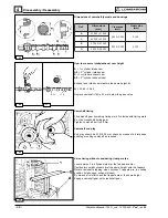
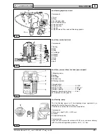
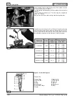
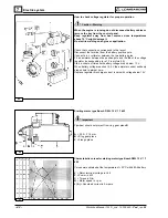
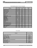
Injection pump delivery setting with engine at the torque
dynamometer
1) Bring engine to idling speed
2) Unscrew delivery limiting device C (see pic. 94)
3) Bring engine to the power and r.p.m. required by the manufacturer
of the device.
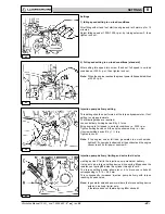
4) Check that consumption falls within the table specifications (see
below).
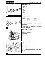
If consumption is not as indicated change balance conditions at the
torque dynamometer by varying the load and adjusting the governor.
Under stable engine conditions check consumption again.
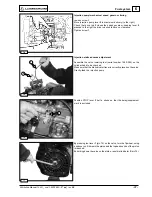
5) Tighten limiting device C until the engine r.p.m. decreases.
Lock the limiting device by means of lock nut.
6) Release brake completely and check at what speed the engine
becomes stable.
Speed governor should comply with the requirements of the class
indicated by the manufacturer of the device.
7) Stop the engine.
8) Check valve clearance when the engine has cooled down.
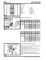
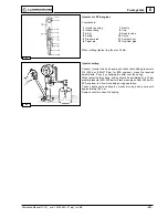
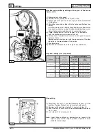
Required settings (most requested)
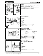
Stop setting
1) Completely turn lever C counterclockwise and keep it in this
posi-tion. Retainer F should not be in contact with lever C.
2) Unscrew nut G and bring retainer F in contact with lever C.
3) Push retainer F so that lever C is moved backwards clockwise by
1.0÷1.5 mm.
4) Lock retainer F by screwing nut G.
Note: Under these conditions no damage can be caused to the
injection pump rack rod stops by sudden impacts due to the
available electric stops.
Settings
Specific fuel consumption
Time (sec)
per 100 cm3
Engine