


- 36 -
Workshop Manual 12 LD _ cod. 1.5302.460 - 3° ed_ rev. 02
3
m m
mm
3
n
o
t
w
e
N
m
m
0
5
,
0
0
1
0
0
5
1
6
2
÷
3
2
3
2
1
0
0
5
8
÷
4
3
0
0
5
1
5
6
÷
7
5
-
0
1
0
0
5
4
1
÷
0
1
3
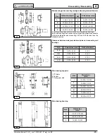
R.P.M.
72
6
71
n
o
t
w
e
N
m
m
0
5
,
0
0
1
0
0
5
1
2
3
÷
9
2
3
2
1
0
0
5
5
1
÷
1
1
3
0
0
5
1
2
7
÷
4
6
-
0
1
0
0
5
4
2
÷
0
2
3
3
m m
mm
3
R.P.M.
73
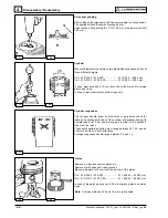
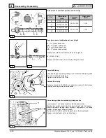
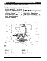
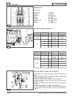
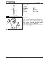
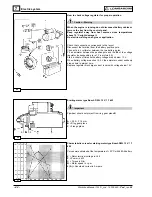
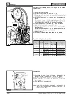
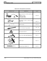
Injection pump
Components:
1 Pump body
10 Plunger
2 Fitting
11 Barrel
3 Seal ring
12 Rack rod
4 Filler
13 Sector gear
5 Shim
14 Spring
6 Spring
15 Upper retainer
7 Delivery valve
16 Lower retainer
8 Seat
17 Tappet
9 Gasket
18 Tappet roller
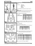
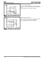
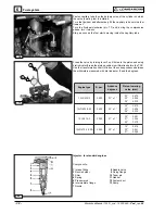
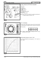
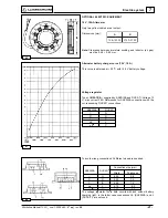
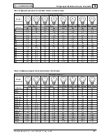
Test data for injection pump delivery
Delivery
Max. plunger
difference
Rod stroke
from max.
deliv. point
Control rod
max. force
stroke
stroke
Delivery
Max. plunger
difference
Rod stroke
from max.
deliv. point
Control rod
max. force
stroke
stroke
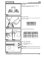
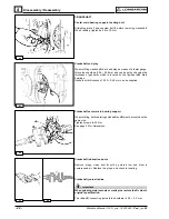
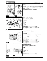
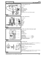
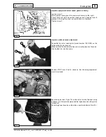
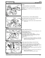
How to reassemble injection pump components
After replacing the worn-out components, reassemble the pump as
follows:
Introduce sector gears into the pump body by making reference points
C match with the B points on the rack.
Fix barrels with the eccentric screws F on the pump body.
Fit valves with seats, springs, tillers and delivery unions tightening
them at 35 ÷ 40 Nm.
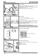
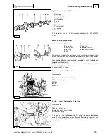
Fit plungers by making reference points E match with the sector gear
D points.
Fix retainers and springs; lock tappet with special stop.
Check that both plungers have the same delivery by performing the
necessary measurements at the test bed; it delivery is not the same set
screw F.
Fuel system