


- 31 -
Workshop Manual 12 LD _ cod. 1.5302.460 - 3° ed_ rev. 02
55
56
57
54
4
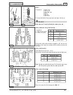
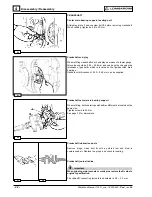
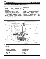
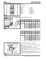
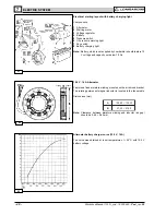
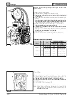
Mechanical speed governor
Components:
1 Gear
6 Lever
2 Fly weight
7 Drive rod
3 Sliding bell
8 Governor spring
4 Stop ring
9 Rack control lever
5 Yoke
Weights are moved to the periphery by the centrifugal force and thus
axially shift a mobile bell connected to the injection pump rack control
lever by a linkage.
A spring placed under tension by the accelerator control offsets the
weights centrifugal force.
Balance between the two forces keeps speed at an almost constant
level in spite of load variations.
See picture 52 for timing.
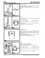
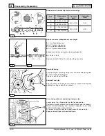
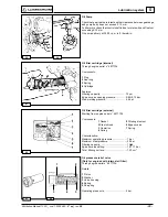
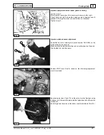
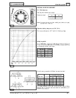
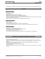
Governor springs with rocker arm
Components:
1 Rocker arm for spring anchoring
2 Governor springs
3 Plate
4 Link
5 Lever
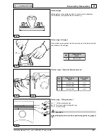
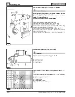
Spring for extra fuel supply at starting
Components:
1 Extra fuel spring
2 Injection pump control yoke
3 Governor spring.
The device is operated automatically: when the engine is stopped
spring 1 acts on injection pump control yoke 2 providing maximum fuel
delivery, until the engine starts and the governor controls the injection
pump rack.
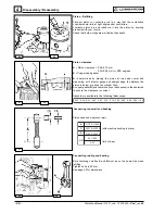
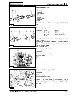
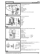
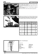
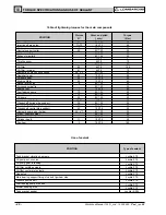
Hydraulic pump p.t.o. (1P)
1 Seal ring
2 Centering ring
3 Coupling
4 Half coupling
5 Flange
6 Gear
7 Bracket
8 Thrust washer
9 Stop ring
10 Cover
The maximum torque is 27 Nm corresponding to 7,64 kW at 3000
r.p.m.
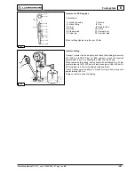
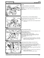
Disassembly / Reassembly