

- 38 -
Workshop Manual 12 LD _ cod. 1.5302.460 - 3° ed_ rev. 02
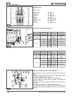
78
79
6
80
2
/
5
3
4
D
L
2
1
0
0
0
3
°
1
±
°
3
2
0
7
5
.
3
°
2
2
4
9
8
.
3
°
3
2
2
3
2
.
4
°
4
2
1
B
-
2
/
5
3
4
D
L
2
1
0
0
6
3
°
1
±
°
3
2
0
7
5
.
3
°
2
2
4
9
8
.
3
°
3
2
2
3
2
.
4
°
4
2
2
-
5
7
4
D
L
2
1
0
0
0
3
°
1
±
°
1
2
1
6
9
.
2
°
0
2
8
5
2
.
3
°
1
2
0
7
5
.
3
°
2
2
A
P
E
2
-
5
7
4
D
L
2
1
0
0
0
3
°
1
±
°
0
2
6
7
6
.
2
°
9
1
1
6
9
.
2
°
0
2
8
5
2
.
3
°
1
2
1
2
4
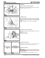
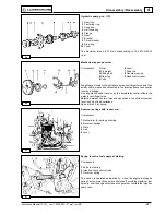
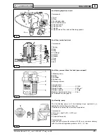
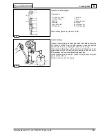
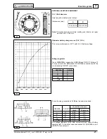
Injector, for standard engines
Components:
1 Intake fitting
8 Needle valve
2 Nozzle holder
9 Fixing flange
3 Shim
10 Taper pin
4 Spring
11 Gasket
5 Pressure rod
12 System duct
6 Intermediate flange
13 Sump
7 Nozzle
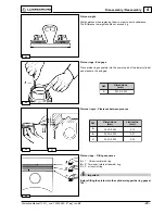
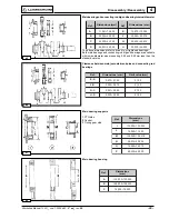
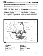
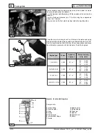
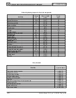
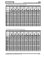
Fuel system
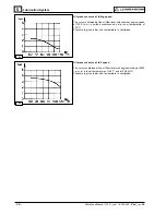
Piston lowering
value (mm)
R.p.m.
Advance
degrees
Engine type
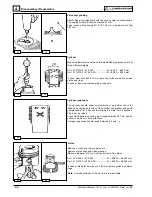
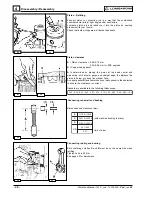
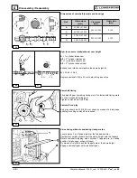
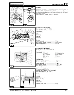
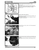
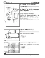
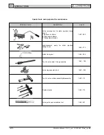
Fasten capillary tube 4 on the delivery union of the cylinder on which
the valve lowering tool is installed.
Turn the flywheel and alternatively fill the capillary tube until the fuel
flows out.
Turn the flywheel clockwise (pic. 77) and, during the compression
phase, turn it slowly.
Stop as soon as the fuel starts moving inside the capillary tube.
Press the valve by turning lever 1 until it meets the piston and using
dial indicator 2 read the piston position in millimetres before the TDC.
Use the transformation chart to find out the correspondence between
the millimeters measured with dial indicator 2 and the degrees.