


- 40 -
Workshop Manual 12 LD _ cod. 1.5302.460 - 3° ed_ rev. 02
A
0
2
,
9
5
1
÷
0
8
,
8
5
1
B
0
9
,
7
2
÷
0
5
,
7
2
83
85
84
7
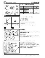
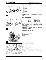
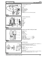
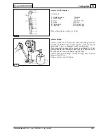
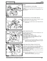
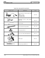
Electrical starting layout with battery charging light
Components:
1 Alternator.
2 Starting motor
3 Voltage regulator
4 Battery
5 Pressure switch
6 Oil pressure warning light
7 Key switch
8 Battery charging light
Note: Battery, which is not supplied by Lombardini, should feature 12
V voltage and capacity not below 70 Ah.
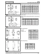
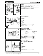
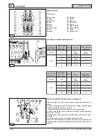
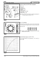
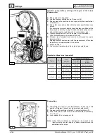
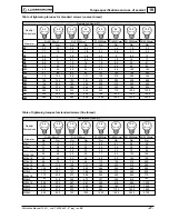
12.5 V, 14 A Alternator
Features a fixed armature winding mounted on the air shroud bracket.
The rotating permanent magnet inductor is located in the fan spindle.
Dimensions (mm):
Note: Clearance between armature winding and inductor (air gap)
should be 0.48 ÷ 0.60 mm.
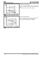
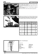
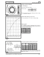
Alternator battery charger curve (12.5 V, 14A)
The curve was obtained at room temperature of + 25°C with 12.5 V
battery voltage
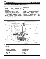
ELECTRIC SYSTEM