


- 22 -
Workshop Manual 12 LD _ cod. 1.5302.460 - 3° ed_ rev. 02
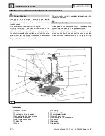
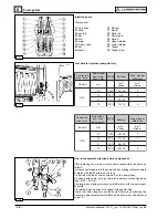
7
8
9
11
4
10
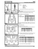
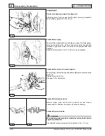
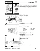
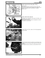
Compression release (optional)
Bring piston to top dead center on the compression stroke.
Unscrew rocker arm cover side plug and measure clearance A, which
must be 0.30÷0.40 mm.
For setting purposes remove rocker arm cover, unscrew lock nut C
and set clearance A by adjusting the screw B.
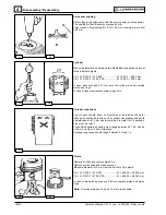
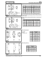
Rocker arm assembly
Components:
1 Bore
2 Lubrification tube
Dimensions (mm):
A = 18.032 ÷ 18.050
B = 17.989 ÷ 18.000
If clearance (A-B) exceeds 0.135 mm replace shaft and rocker arms.
When refitting check that lubrication tube perfectly matches with the
journal bore.
Tighten screws to 25 Nm.
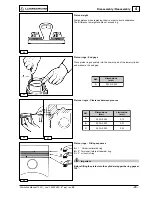
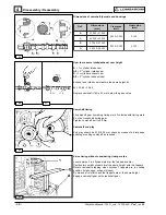
Injector projection
The end of nozzle A should project 3.0 ÷ 3.5 mm (2,00÷2,50mm for
EPA engines) from the cylinder head plane.
Adjust injector projection by means of copper shims B measuring 1.5
and 1.00 mm in thickness.
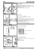
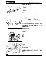
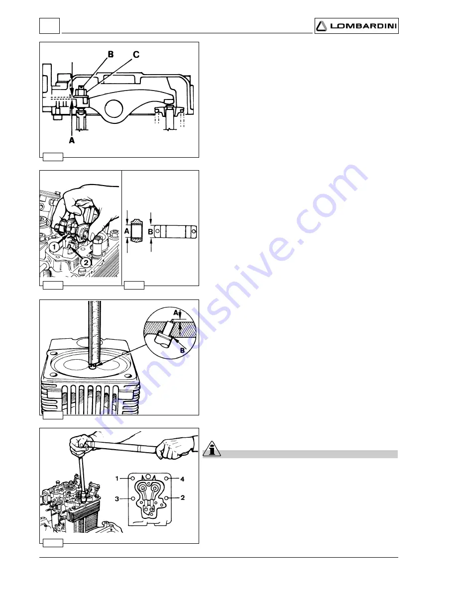
Cylinder Head
Important
Do not remove it when hot to avoid deformation.
If cylinder head is deformed level it hot by removing a maximum of 0.3
mm.
When refitting tighten only if sure that rocker arm lubrication tube is
well inside its holes and that both heads are in line by fitting the inlet
and exhaust manifolds before tightening the cylinder head nuts.
Always replace copper head gasket: see page 26 (picture 32) for
choosing the right thickness.
Progressively tighten nuts in the 1, 2, 3, 4 sequence at 50 Nm.
Disassembly / Reassembly