background image

Logosol Multifunctional Servo Drive LS-231SE 

Doc # 712231004 / Rev. A, 05/05/2011 


Logosol, Inc. 

 1155 Tasman Drive 

 Sunnyvale, CA 94089 Tel: (408) 744-0974 

 www.logosolinc.com


26

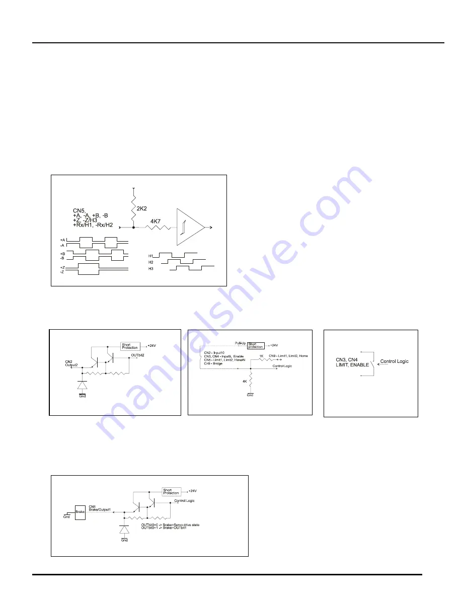
Encoder and Commutator interface 

The Encoder interface accepts two square wave inputs – +A, +B (+A, -A, +B, and -B for differential 
encoders) from an incremental encoder. Ideally these square waves are 50% duty cycle and +/-90 
degrees out of phase. The time between encoder state transitions is limited and should not be less than 
0.1uS when encoder filter is off and 0.2uS when encoder filter is on. With ideally formed encoder pulses, 
this would correspond to a 2500 line encoder (10000 counts/rev) rotating at 60,000/30,000 rpm. Refer to 
Logosol Quick start guide / Motor initialization to select the encoder mode. 
Encoder Index +Z (+Z and –Z for differential encoders) is used by Servo control module to capture 
Home position. 
Hall sensors provide the motor position. They are used by motor control module to determine motor 
position after power up and during the motor initialization procedure. 


Besides the position control, encoder phases, index and hall sensors are used to determine the motor 
commutation synchronizing the output PWM every motor rotation according to hall and encoder data.  

Control interface 


Refer to 

Safety Features - LS-231SE diagnostic and I/O 

section for inputs/outputs descriptions.   

Brake/Output1 

When OUTbit0=1 Brake/Output1 follows the state of OUTbit1.  
When OUTbit0=0 Brake/Output1 follows the Servo drive state described in 

LS-231SE Diagnostic and 

I/O

. Brake current must not exceed 0.3A 


Encoder and Commutator interface


Brake/Output1 


Outputs - Safety bus 


Input interface 


Output interface 

Summary of Contents for LS-231SE

Page 1: ...amplifier designed for applications requiring sinusoidal control of Rotary or Linear brushless motors up to 1 5 HP DC brush and Voice coil motors are also supported In LDCN mode the drive supports coo...

Page 2: ...1 5V 2K2 pull up resistors LOmin 0 5V LO 6 5V 15V HI HImax 36V Imax 8mA HI 3 5V LO 1 5V 4K7 pull down resistors ANALOG INPUT ADCin 10V 10K to Gnd ENCODER Quadrature with index Encoder rate 10MHz max 5...

Page 3: ...50 max 0 165 0 500 0 850 SERVO DRIVE LAYOUT ORDERING GUIDE PART NUMBER MODEL DESCRIPTION 912231010 LS 231SE 2020 Multifunctional servo drive 20A 180V 230601051 LS 231 CN Mating connector kit for LS 23...

Page 4: ...de Sw6 OFF Sw5 OFF Reserved CONNECTORS CN1 POWER AND MOTOR PIN SIGNAL DESCRIPTION 1 POWER 18Vdc TO 90Vdc Power supply positive terminal 2 24V 18Vdc TO 36Vdc I O power supply 3 POWER Gnd Power supply g...

Page 5: ...motors Encoder index Z for Panasonic A or S series motors and DC motors with differential encoder 4 B NA Encoder phase B for motors for motors with differential encoder 5 A NA Encoder phase A for moto...

Page 6: ...Step Positive Step Negative mode Negative Step input Quadrature encoder mode Counter A input 8 Gnd Signal ground 9 Fault Fault output 10 Gnd Signal ground 11 5V 5V power supply 12 AEN LDCN Single loop...

Page 7: ...rive Sunnyvale CA 94089 Tel 408 744 0974 www logosolinc com 7 DUAL LOOP MASTER ENCODER INTEFRACE LS 231SE1 is master encoder interface for dual loop applications with LS 231SE Multifunctional Servo Dr...

Page 8: ...must be shorted DIP SWITCHES SWITCH NAME DESCRIPTION 1 Reserved Reserved must be OFF 2 Reserved Reserved must be OFF CN1 PIN SIGNAL DESCRIPTION 1 12Vdc to36Vdc Power supply input If Power source jumpe...

Page 9: ...output 10 Gnd Power supply ground 11 5V 5V Power Supply output 12 AEN Amplifier Enable input 13 NC Not connected 14 AnGnd Analog ground Wired to CN4pin14 15 ADCin Analog input Wired to CN4pin15 16 DA...

Page 10: ...12231004 Rev A 05 05 2011 Logosol Inc 1155 Tasman Drive Sunnyvale CA 94089 Tel 408 744 0974 www logosolinc com 10 SAMPLE APPLICATION using AC brushless motor in LDCN mode Home switch and limit switche...

Page 11: ...12231004 Rev A 05 05 2011 Logosol Inc 1155 Tasman Drive Sunnyvale CA 94089 Tel 408 744 0974 www logosolinc com 11 SAMPLE APPLICATION using AC brushless motor in LDCN mode Home switch and limit switche...

Page 12: ...nal Servo Drive LS 231SE Doc 712231004 Rev A 05 05 2011 Logosol Inc 1155 Tasman Drive Sunnyvale CA 94089 Tel 408 744 0974 www logosolinc com 12 SAMPLE APPLICATION using Panasonic A or S series motors...

Page 13: ...LS 231SE Doc 712231004 Rev A 05 05 2011 Logosol Inc 1155 Tasman Drive Sunnyvale CA 94089 Tel 408 744 0974 www logosolinc com 13 SAMPLE APPLICATION using Panasonic A or S series motors in Step Directi...

Page 14: ...S 231SE Doc 712231004 Rev A 05 05 2011 Logosol Inc 1155 Tasman Drive Sunnyvale CA 94089 Tel 408 744 0974 www logosolinc com 14 SAMPLE APPLICATION using Panasonic A or S series motors in Quadrature enc...

Page 15: ...Servo Drive LS 231SE Doc 712231004 Rev A 05 05 2011 Logosol Inc 1155 Tasman Drive Sunnyvale CA 94089 Tel 408 744 0974 www logosolinc com 15 SAMPLE APPLICATION Analog Input Dual Loop mode using Panason...

Page 16: ...408 744 0974 www logosolinc com 16 SAMPLE APPLICATION LDCN Dual Loop mode using AC brushless motor Home switch and limit switches are connected to CN5 CN5 8 NETWORK HOST Enable Stop 24V B R NETWORK S...

Page 17: ...408 744 0974 www logosolinc com 17 SAMPLE APPLICATION LDCN Dual Loop mode using AC brushless motor Home switch and limit switches are connected to CN8 CN5 8 NETWORK HOST Enable Stop 24V B R NETWORK S...

Page 18: ...n Drive Sunnyvale CA 94089 Tel 408 744 0974 www logosolinc com 18 SAMPLE APPLICATION LDCN mode using Master and Slave motors NETWORK HOST NETWORK SLAVE NETWORK HOST NETWORK SLAVE CN8 2 A CN8 4 B CN8 9...

Page 19: ...4 www logosolinc com 19 SAMPLE APPLICATION Analog input using Master and Slave motors CN8 2 A CN8 4 B CN8 9 Fault CN8 8 GND CN8 7 DIR CN8 8 GND CN8 12 AEN CN8 13 STEP CN8 4 B CN8 2 A CN8 8 GND CN8 15...

Page 20: ...Brake Yellow EXTENSION CABLE To LS 231SE MOTOR CONNECTOR AMP CAP 172163 1 10 pins 170365 1 LS 231SE CONNECTOR AMP 205206 3 D Shape 15 Pin Male Crimp Housing 15 pins AMP 5 66507 7 PIN SIGNAL NAME PIN...

Page 21: ...tributed Control Network Utility installation disk into the floppy drive 2 Select RUN from the Windows 95 98 2000 NT XP Start Menu 3 Type a dcnsetup and then click OK a represents the drive letter 4 T...

Page 22: ...us current Overload time the drive output will be limited to this value for overload time After the expiring of the Overload time the output will be disabled If Off is set the drive output will not be...

Page 23: ...f the sample applications described earlier 3 Turn on the power supply and run LDCN Utility 4 While still in single loop mode run the motor and make sure the auxiliary encoder position on the screen c...

Page 24: ...direction Scale is the factor used to convert the analog input value 32768 to 32767 to velocity For example scale of 10 produces maximum velocity of 327670 or 97653 encoder counts per second 327670 3...

Page 25: ...TURE Overview LS 231SE Logosol Multifunctional Servo Drive is a highly integrated servo control module for Brushless motors including motion controller servo amplifier with integrated sinusoidal outpu...

Page 26: ...zation to select the encoder mode Encoder Index Z Z and Z for differential encoders is used by Servo control module to capture Home position Hall sensors provide the motor position They are used by mo...

Page 27: ...supports full duplex multi drop RS 485 interface that allows multiple drives to be controlled over a single RS 485 port The host sends commands over it s RS 485 transmit line and receives all status...

Page 28: ...onnecting A out pin to the A in pin of the next servo drive in the network will enable its communication at default address of 0x00 Repeating this process allows a variable number of controllers prese...

Page 29: ...of 40 rev sec sec which would bring us up to the desired speed in sec would be 0 00021 counts tick tick with the lower 16 bits the fractional component this would be programmed as 0 00021 x 65536 or 1...

Page 30: ...tic For better control Safety bus can be connected to SK 2310 or other controller with similar functions FAULT output depends on internal drive status Refer to LS 231SE Diagnostic and I O for details...

Page 31: ...s Bit 3 Power Status Bit 0 Move_done Auxiliary Bit 2 Servo Auxiliary Bit 0 Index DE INbit12 CONDITION ORANGE GREEN RED FAULT RELAY BRAKE OUTbit0 0 Limit2 Source Home Source X 1 X 1 Encoder 1 ServoON O...

Page 32: ...ake Output1 is following Output1 bit Bit 0 Brake Outpu1 CN1pin4 OFF Bit 1 Brake Outpu1 CN1pin4 HIGH OUTbit2 Output2 CN2pin3 Bit 0 Output2 OFF Bit 1 Output2 HIGH OUTbit3 N A Reserved clear to 0 OUTbit4...

Page 33: ...de pulse Dir CN8pin7 INbit14 0 Master encoder counter phase A CAP4 Step CN8pin13 N A Master encoder counter phase B CAP5 _____ Fault CN8pin9 N A SW4 OFF HIGH when PIC_AE bit is CLEARED Power driver is...

Page 34: ...n DE is LOW or fault condition is present HIGH when DE is HIGH and NO fault condition is present Step Dir mode MODEbit C B A 110 Name Bit DE INbit12 AEN CN8pin12 INbit7 Dir CN8pin7 INbit14 0 AEN CN8 1...

Page 35: ...s the path mode As the buffers becomes depleted additional path points are dynamically added while the axes are still in motion until the path is complete The timing requirements for the host require...

Page 36: ...starting at exactly the same time When a start path command is issued to a group of controllers they will all start within 0 000025 seconds of one another The second type of timing error results from...

Page 37: ...equency Yes Set home mode 0x9 1 Sets conditions for capturing the home position Yes Set baud rate 0xA 1 Sets the baud rate group command only Yes Clear bits 0xB 0 Clears the sticky status bits Yes Sav...

Page 38: ...0 send position 4 bytes 1 send A D value 1 byte 2 send actual velocity 2 bytes no fractional component 3 send auxiliary status byte 1 byte 4 send home position 4 bytes 5 send device ID and version num...

Page 39: ...nd value 0x4 Number of data bytes n 1 15 Command byte 0xn5 Data bytes 1 Control byte Bit 0 load position data n n 4 bytes 1 load velocity data n n 4 bytes 2 load acceleration data n n 4 bytes 3 load P...

Page 40: ...bytes of acceleration data Start Motion Command value 0x5 Number of data bytes 0 Command byte 0x05 Description Causes the trajectory information loaded with the most recent Load Trajectory command to...

Page 41: ...the profiling modes it will stop moving abruptly and servo to its current position This stopping mode should only be used as an emergency stop where the motor position needs to be maintained Setting b...

Page 42: ...or occurs 7 Capture home position when current limiting occurs Description Causes the Drive to monitor the specified conditions and capture the home position when any of the flagged conditions occur T...

Page 43: ...ositions can then be read individually by reading the home position Add path points Command value 0xD Number of data bytes n 0 2 4 6 8 10 12 or 14 Command byte 0xnD Data bytes 1 2 Incremental data for...

Page 44: ...motor will simply start servoing to its current position Setting bit 3 enters a more graceful stop mode the controller sets the goal velocity to 0 and enters velocity mode causing the motor to deceler...

Page 45: ...activated the status will be 65535 0xFFFF If the watchdog has expired the status will be 0 Any other value means that the watchdog is working and represents the remaining time before the watchdog exp...

Page 46: ...o LS 231SE Diagnostic and I O section in this document 7 Home_in_progress Set while searching for a home position Reset to zero once the home position has been captured Auxiliary Status Byte Bit Name...

Page 47: ...t command Status Byte s Note During the communication all bytes are sent with LSB first Commands There are 16 commands managing Servo drives refer to Command Description Each command as shown in the f...

Page 48: ...d code Individual Address Group Address Checksum AA 00 21 01 FF 21 Setting the Addresses After power up and Hard Reset command all drives have their address set to 00h and only the first drive startin...

Page 49: ...an Drive Sunnyvale CA 94089 Tel 408 744 0974 www logosolinc com 49 The flowchart shows the addressing procedure of N drives network There is no group leader and the group address is FF I Individual Ad...

Page 50: ...nes PID parameters KP 64h KD 400h KI 00h IL 00h OL FFh CL 00h EL 800h SR 01h DC 00h 6 AA 01 E4 9F 00 00 00 00 00 00 00 00 01 00 00 00 00 85 Load trajectory for drive 1 target position 0 velocity 0 acc...

Page 51: ...1 00 22 00 00 00 19 Load trajectory Velocity mode Forward direction Velocity 1 revolution per second 67109 programmed velocity for 5000 line encoder Acceleration 10 revolutions per second2 34 programm...

Reviews: