28
9.2. Wiring Diagram:
Calculate the right CT and PT required based on your load and voltage
levels to bring current and voltage in the input range of the energy meter
(6A current and 350 L-N Voltage). Install the CT and PT as per the diagram
below.
9.2.1
3 Phase 4 wire Syste
m
Fig 1 Connection diagram 3 phase 4 wire using 3 PTs, 3CT
Fig 2 Connection Scheme 3 phase 4 wire using, 3CTs
Summary of Contents for EnergyLogicIQ
Page 1: ...2018 LogicLadder Instruction Manual EnergyLogicIQ Generator Monitoring System Version 12 2017...
Page 2: ......
Page 16: ...11...
Page 17: ...12 7 EnergyLogicIQ IoT Cloud Connector A Top View B Top Side View...
Page 18: ...13 C Left Side View D Bottom Side View...
Page 24: ...19 7 8 Connecting Generator On Off Signal and Run Hours...
Page 38: ...33 2 Setup communication parameter...
Page 40: ...35 10 2 Scenario 2 1 Generator 2 Tanks 10 3 Scenario 3 2 Generator 2 Tanks Internal Tanks...
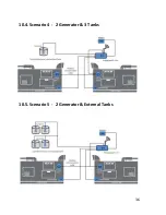
Page 41: ...36 10 4 Scenario 4 2 Generator 3 Tanks 10 5 Scenario 5 2 Generator External Tanks...
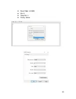
Page 48: ...43 Baud Rate 115200 Bit 8 Stop Bit 1 Parity None...
Page 50: ...45 13 Declaration of Conformity...
Page 51: ...46...
Page 52: ...47...
Page 54: ......


