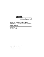
7. The
Confirm New Settings
screen will appear (shown in Figure 7-15). To
save the new settings, click the
Yes
button. To cancel the settings and return
to the
P r o f i l e s
screen, click
the
Cancel
button. To
edit the new
s e t t i n g s ,
click the
Back
button.
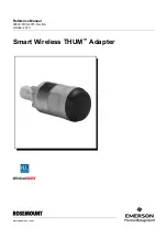
8. The
Congratulations
screen (Figure 7-16) will appear next. Click
Activate
new settings now
to implement the new settings immediately and return to
the
Link Information
screen. Click
Activate new settings later
to keep the
current settings active, and return to the
Profiles
screen so that you can edit
your profile
or create
another profile.
You have successfully created a connection profile. Click the X (Close) button
in the upper right corner to exit the WLAN Monitor.