


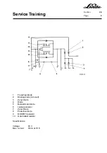


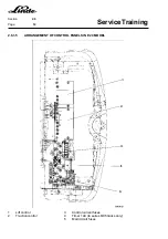

Service Training
Section
2.5
Page
4
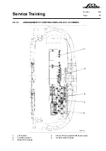
2.5.2
BRAKING
2.5.2.1
RENEWING THE BRAKE LININGS
The brake linings must be replaced when the linings are 2 mm thick at the thinnest point.
- Open and tilt the overhead guard to the second detent.
- Loosen the locknut (3) on the handbrake lever (1) and the adjusting nut (2) on the parking brake cable (4).
- Unhook the handbrake cable (4) at the brake shoes (5) and (6).
- Remove one pin retainer (10) on each of the two brake shoes (5) and (6).
- Tilt the brake shoes up.
- Remove the fastening screws (7) for the brake shoes (8).
- Fit new brake shoes (8).
- Fit handbrake cable
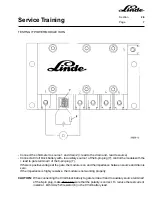
2.5.2.2
ADJUSTING THE FOOT BRAKE
The foot brake can be adjusted if the brake linings are worn.
- Open and tilt the overhead guard to the second detent.
- Slowly press the lever (9) with the hand.
- The lever must then be approx. 20 mm from the end stop of the lever.
- For the adjustment, loosen the locknut (12) at the threaded pin (11) and adjust the threaded pin.
- Tighten the locknuts (12) again.
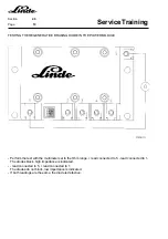
2.5.2.3
ADJUSTING THE HANDBRAKE
Open and tilt the overhead guard to the second detent.
- Slowly engage the handbrake (1) while watching lever (9).
- The lever must move jointly with the handbrake lever until the point of higher spring pressure (brake lining
contacts the brake disc) is reached.
- Release the release button.
- The brake must be applied when the handbrake has clicked five times.
- If an adjustment is necessary, loosen the locknut (3) for the handbrake cable on the handbrake lever to
adjust the tension of the handbrake cable (4) with the adjusting nut (2).
Summary of Contents for 336 Series
Page 2: ......
Page 8: ...ServiceTraining ...
Page 12: ...ServiceTraining Section 2 1 Page 4 ...
Page 14: ...ServiceTraining Section 2 1 Page 6 2 1 4 TRACTIONMOTORDISASSEMBLY ...
Page 19: ...ServiceTraining Section 2 2 Page 3 ...
Page 21: ...ServiceTraining Section 2 2 Page 5 ...
Page 27: ...ServiceTraining Section 2 2 Page 11 ...
Page 28: ...ServiceTraining Section 2 2 Page 12 ...
Page 33: ...ServiceTraining Section 2 4 Page 1 2 4 STEERING SYSTEM ...
Page 35: ...ServiceTraining Section 2 4 Page 3 ...
Page 37: ...ServiceTraining Section 2 4 Page 5 ...
Page 39: ...ServiceTraining Section 2 4 Page 7 ...
Page 41: ...ServiceTraining Section 2 4 Page 9 ...
Page 45: ...ServiceTraining Section 2 4 Page 13 ...
Page 47: ...ServiceTraining Section 2 4 Page 15 ...
Page 53: ...ServiceTraining Section 2 5 Page 5 ...
Page 54: ...ServiceTraining Section 2 5 Page 6 ...
Page 69: ...ServiceTraining Section 2 6 Page 15 ...
Page 74: ...ServiceTraining Section 2 6 Page 20 2 6 2 3 CIRCUIT BREAKER CONTACTOR 1K6 Circuit diagram ...
Page 94: ...ServiceTraining Section 2 6 Page 40 ...
Page 111: ...ServiceTraining Section 2 6 Page 57 Connector 1X6 1 15 V 2 Output signal 3 ...
Page 126: ...ServiceTraining Section 2 6 Page 72 2 6 9 2 LOCATION OF CONNECTORS FROM SERIES 7 95 ...
Page 128: ...ServiceTraining Section 2 6 Page 74 ...
Page 145: ...Section 2 6 Page 91 ...
Page 146: ......
Page 147: ......
Page 149: ...Section 2 6 Page 93 ...
Page 150: ......
Page 153: ...ServiceTraining Section 2 7 Page 3 ...
Page 157: ...ServiceTraining Section 2 7 Page 7 ...
Page 158: ...ServiceTraining Section 2 7 Page 8 ...
Page 163: ...Section 2 9 Page 5 ...
Page 164: ......
Page 166: ...ServiceTraining Section 2 10 Page 2 ...
Page 167: ......